Engineering guide to Installing Solar Panels on a Metal Roof — standing seam vs corrugated, S-5! clamps, wind uplift calculations & non-penetrating mounting. Written by a Registered PE.
Metal roofs and solar panels are a natural engineering combination — yet I see more specification errors in metal roof installations than in any other roof type. Not because metal roof solar is technically difficult. Because it is fundamentally different from asphalt shingle installation, and too many solar installers treat every roof the same.
The core differences are structural and material: standing seam metal roofs attach solar without a single roof penetration. Corrugated profiles require penetrations but offer excellent structural backing through their purlin systems. Both have thermal expansion characteristics that create loading conditions absent on static asphalt surfaces. And the clamp and bracket systems approved for metal roof installation are categorically different from the lag-bolt-and-rail systems used on shingle roofs — they are profile-specific, load-tested to ASCE 7 protocols, and non-interchangeable with generic hardware.
Get the specification right, and a metal roof solar is the most durable, leak-free, and structurally sound installation type available. Get it wrong, and you have a noise problem, a leak problem, or a structural problem within the first few thermal cycles. This guide covers the engineering of metal roof solar the way it should be taught.
1. Why Installing Solar Panels on a Metal Roof Is Exceptionally Well-Suited for Solar
Structural Strength
Metal roofing systems — standing seam steel, corrugated steel, or aluminum panels — are mechanically stiffer than asphalt shingles by a significant margin. The underlying structure required for a metal roof is typically heavier gauge and more closely spaced than for asphalt, meaning metal-roofed buildings frequently have more reserve structural capacity for solar dead loads. This is not universal — always verify with a structural analysis — but it is a consistent and reliable pattern across the project types I have reviewed.
Roof Longevity Match
Asphalt shingles last 20 to 30 years. A solar system lasts 25 to 30 years. Installing solar on a 15-year-old asphalt roof almost guarantees you will need to remove the array for reroofing midway through the system’s life — a labor cost of $3,000 to $8,000 plus schedule disruption. A quality standing seam metal roof lasts 40 to 70 years. The solar power system retires before the roof does. This eliminates the mid-life reroof scenario and is one of the strongest financial arguments for metal roof solar that most sales processes never surface.
True Non-Penetrating Installation
Standing seam metal roofs are the only common residential roof type where high-quality, structurally sound solar installation is achievable without a single roof penetration. The seam clamp system locks onto the raised standing seam mechanically — no drilling, no sealants at attachment points, no leak risk at the solar mounting hardware. For homeowners who cite roof leak concern as the primary hesitation about solar, a standing seam roof eliminates that concern when properly installed.
Thermal Environment for Wiring
Metal roofs run 50 to 60°F cooler than dark asphalt in direct sun. The underside air temperature where solar panel DC wiring runs is correspondingly lower, which extends wire insulation life and reduces the ambient temperature around the panel junction boxes. Panels operate at lower cell temperatures on metal roofs than on dark asphalt, translating to marginally higher electrical efficiency across the system’s life.
1B. Why Bifacial TOPCon N-Type Solar Panels Perform Best on Metal Roofs
Metal roofs are not just compatible with bifacial solar panels — they are the optimal substrate for them. And within the bifacial category, TOPCon N-type technology extracts more value from a metal roof’s unique characteristics than any other panel technology available in 2026. This is one of the most underappreciated engineering advantages of metal roof solar, and it is almost never discussed in residential solar sales conversations.
How Bifacial Panels Work — And Why Cell Technology Matters
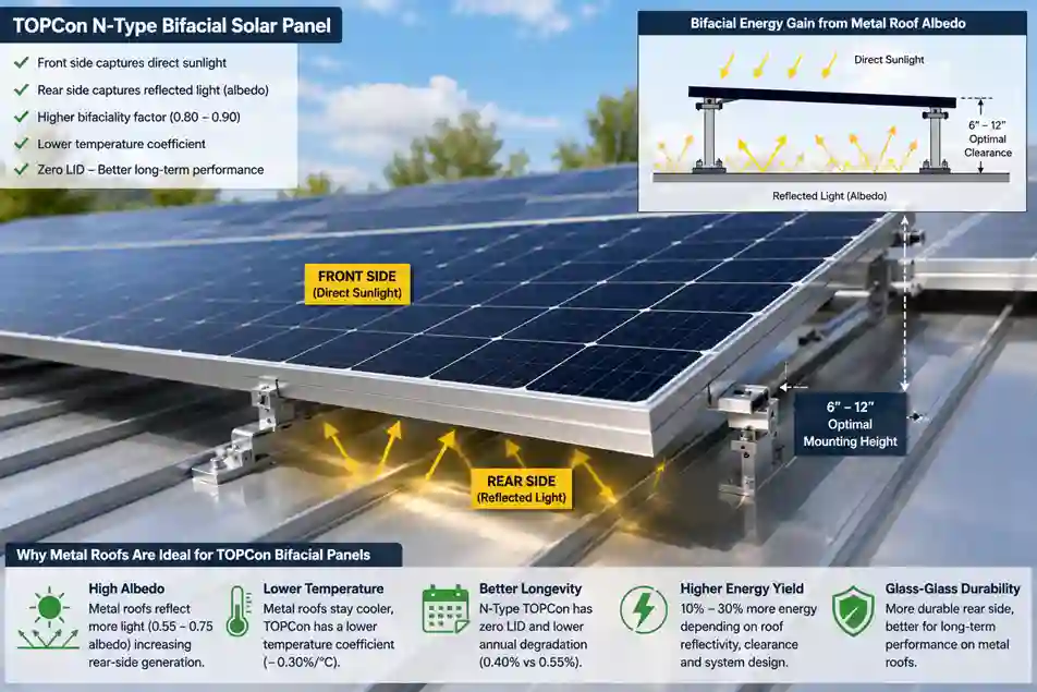
Bifacial solar panels generate electricity from both the front face and the rear face. The front captures direct sunlight exactly as a standard monofacial panel does. The rear face captures reflected light — albedo — bouncing off the roof surface below. The split is governed by the panel’s bifaciality factor. This is where cell technology matters critically.
TOPCon N-type panels deliver three compounding advantages on metal roofs specifically:
Highest bifaciality factor in volume production — 0.80 to 0.90, meaning the rear face produces 80 to 90% of what the front face would under identical irradiance. Combined with metal roof albedo, this is where the production gains become substantial.
Superior temperature coefficient — metal roofs run 50 to 60°F cooler than dark asphalt, which benefits all panels. TOPCon’s lower temperature coefficient (−0.30%/°C vs. PERC’s −0.38%/°C) extracts more value from every degree of cooling. On a hot summer day where cell temperature is 20°C above STC, TOPCon loses 6% output versus PERC losing 7.6% — a 1.6 percentage point efficiency advantage that compounds across 25 years.
Zero LID on N-type substrate — Light-Induced Degradation (LID) causes 1 to 3% permanent output loss in P-type silicon panels during the first 100 to 200 hours of sunlight exposure. N-type silicon — the substrate in TOPCon and HJT — is structurally immune to LID. Combined with a lower annual degradation rate (0.40% for TOPCon vs. 0.55% for PERC), this produces measurably more energy over the system’s life.
Metal Roof Albedo — The Multiplier That Makes Bifacial Worth It
The rear-side gain from any bifacial panel depends entirely on the reflectivity of the surface below. This is where metal roofs separate themselves from every other common roofing material.
| Roof Surface | Albedo Coefficient | Rear-Side Gain (TOPCon BF 0.85) |
|---|---|---|
| White / light-painted metal roof | 0.60–0.75 | 20–28% additional rear gain |
| Galvalume unpainted steel | 0.55–0.70 | 18–25% additional rear gain |
| TPO white membrane (flat commercial) | 0.65–0.80 | 22–30% additional rear gain |
| Dark painted metal (charcoal, bronze) | 0.15–0.25 | 6–10% additional rear gain |
| Standard dark asphalt shingle | 0.05–0.15 | 2–5% additional rear gain only |
| Concrete tile (terracotta) | 0.20–0.30 | 7–11% additional rear gain |
A TOPCon bifacial panel on an unpainted Galvalume roof captures rear-side irradiance at 5 to 10 times the rate of the same panel on dark asphalt. On a well-designed 8 kW system this translates to 900 to 1,800 additional kWh annually — with zero additional panels, zero extra roof penetrations, and zero additional structural loading.
Mounting Height and Rear-Side Irradiance
Rear-side gain is directly affected by panel clearance above the roof surface. Rail shadows at low clearance reduce reflected light reaching the rear cells:
- Minimum clearance for bifacial: 4 inches above roof surface
- Optimal clearance: 6 to 12 inches for uniform rear-face irradiance
- Rail shadow penalty at 4 inch clearance: reduces rear gain by 10 to 15%
- Rail shadow penalty at 8 inch clearance: drops to 3 to 5%
Standard S-5! raised rail configurations accommodate this clearance naturally — one reason the S-5! clamp-and-rail system is particularly well-matched to TOPCon bifacial installations on standing seam metal roofs.
Calculating Your TOPCon Bifacial Gain
The industry-standard formula:
Rear-side gain (%) = Bifaciality Factor × Albedo × View Factor × 100
Where View Factor (typically 0.55 to 0.75) accounts for mounting height, row spacing, and structural shading.
Worked example — TOPCon on unpainted Galvalume, 8 inch clearance:
Rear-side gain = 0.85 × 0.65 × 0.70 = 38.7% of front-side output contributed by rear face
On a system producing 10,000 kWh annually from the front face, this adds approximately 3,870 kWh — equivalent to nearly 2.5 additional panels with no extra roof penetrations, no structural loading increase, and no additional clamp points.
Engineer’s Note: When I review bifacial TOPCon proposals for metal roof installations remotely, the first number I check is the albedo input in the production model. PVWatts defaults to 0.20 — approximately correct for dark asphalt. On a light Galvalume or white-painted metal roof the correct input is 0.60 to 0.75. Using the default underestimates annual production by 10 to 18% on a TOPCon bifacial system. Ask your installer specifically: what albedo value is in your PVWatts model, and does it reflect the actual color and coating of my metal roof? If they cannot answer that question, they have not properly modeled a bifacial system
Recommended TOPCon N-Type Bifacial Panels for Metal Roofs (2026)
| Panel Model | Bifaciality Factor | Temp Coefficient | Construction | Efficiency |
|---|---|---|---|---|
| LONGi Hi-MO 6 | 0.85 | −0.29%/°C | Glass-glass | 22.8% |
| Jinko Tiger Neo N-type | 0.82 | −0.30%/°C | Glass-glass | 22.5% |
| Canadian Solar BiHiKu7 TOPCon | 0.80 | −0.30%/°C | Glass-backsheet | 22.1% |
| REC Alpha Pure-R (HJT) | 0.92 | −0.24%/°C | Glass-glass | 23.0% |
| Risen Titan S TOPCon | 0.82 | −0.30%/°C | Glass-glass | 22.3% |
Specify glass-glass construction for metal roof installations — more durable rear face, better suited to the elevated thermal cycling environment, and higher bifaciality factors than glass-backsheet equivalents. All five models above are compatible with S-5! clamp systems and standard metal roof rail configurations.
2. Standing Seam vs. Corrugated Metal — The Engineering Difference
Metal roofing falls into two fundamentally different profile categories that require completely different mounting approaches. Applying the wrong mounting method to the wrong profile is the most consequential specification error in metal roof solar.
Standing Seam Profiles
Standing seam panels have raised seams — typically 1 to 1.75 inches — that interlock vertically and run continuously from ridge to eave. The seam is both the structural element and the weatherproofing boundary of the panel system. Standing seam profiles include:
- Snap-lock seam: Most common residential type. Upper panel snaps over the lower seam mechanically. Cannot be separated without specialized tooling — the seam is permanent.
- Mechanically seamed (single or double fold): Seam is folded flat with a seaming machine during installation. Maximum water resistance. Common in commercial and steep-slope residential.
- T-seam / batten seam: Raised rectangular batten profile. Less common; requires profile-specific clamp design.
All standing seam profiles share the critical characteristic: the seam is the solar attachment point. No penetrations. No sealants at mounting locations. No leak risk from the solar installation.
Corrugated and Exposed Fastener Profiles
Corrugated metal, R-panel, and PBR panel systems use exposed fasteners that penetrate the metal panel and attach to structural purlins below. The fasteners are sealed with rubber washers and EPDM gaskets. Solar mounting on these profiles requires penetrating the metal panel at each mounting foot — which means waterproofing at every attachment point is a critical design element, not an afterthought.
| Profile Type | Solar Attachment Method | Penetrations Required | Leak Risk | Recommended System |
| Standing seam — snap-lock | Seam clamp (mechanical, profile-matched) | Zero | None at attachment points | S-5! clamp + rail or direct-attach |
| Standing seam — mechanical seam | Seam clamp (profile-matched — different from snap-lock) | Zero | None at attachment points | S-5! U-series or equivalent |
| Corrugated / R-panel / PBR | L-foot through-fastener into purlin | Yes — one per mounting foot | Low — with stainless hardware + EPDM + compatible sealant | Corrugated L-foot + rail |
| Metal shingle / stone-coated steel | Lag bolt into rafter with flashing | Yes — standard residential method | Low — with proper flashing protocol | Standard rail system, the asphalt-shingle method applies |
Engineer’s Note: A snap-lock clamp must never be used on a mechanically seamed roof — and vice versa. These clamps are profiled to specific seam geometries. A clamp designed for a 1″ snap-lock seam applied to a 1.5″ mechanical seam does not achieve its rated holding force — sometimes by a factor of 2 to 3. Profile verification against the roof manufacturer’s panel specification is mandatory before specifying any clamp system.
3. Approved Clamp and Bracket Systems for Standing Seam Roofs
The standing seam clamp market has a clear industry leader with published engineering data — and several viable alternatives. This is not a component to improvise. The structural adequacy of your entire solar installation depends on whether the specified clamp achieves its rated holding force on your specific seam profile and panel gauge.
S-5! Clamp System
S-5! (S-5! Metal Roof Innovations, Colorado Springs, CO) is the most widely specified and independently tested clamp system in the US market. Their product line covers virtually every standing seam profile and seam height combination, with load testing performed to ASCE 7 protocols and published for each clamp model and metal panel gauge combination.
| S-5! Model | Compatible Seam | Seam Height | Rated Uplift Load | Common Application |
| S-5-S Mini | Snap-lock | < 1″ height | Up to 690 lbs (gauge-dependent) | Low-profile residential snap-lock |
| S-5-S | Snap-lock | 1″–1.75″ | Up to 890 lbs | Standard residential snap-lock — most common |
| S-5-U | Mechanical seam | 1″–1.75″ | Up to 1,240 lbs | Commercial mechanical seam — highest rated |
| S-5-N | T-bar / batten | 1″–1.5″ | Up to 750 lbs | Batten seam profiles |
| S-5-VersaBracket | Universal rail attachment | N/A | N/A | Module and rail integration accessory |
Critical detail: S-5! load ratings are tested for specific metal panel gauges and alloys. A 26-gauge Galvalume steel panel produces different clamp holding forces than a 24-gauge aluminum panel. Your installer must cross-reference the clamp model against the correct load table for your specific roof panel specification — not the generic maximum rating on the product page.
Other Engineered Systems
- SnapNrack Metal Roof Series: Rail-based system with clamps compatible with major snap-lock profiles. Good integration with standard module-level hardware.
- Unirac SolarMount: Metal-roof-specific attachments for both standing seam and corrugated. Well-documented for AHJ submission packages.
- IronRidge XR with metal roof attachments: Widely used residential rail system with metal roof clamp options — verify compatibility with specific seam profile before specifying.
- Roof manufacturer proprietary systems: MBCI, Metal Sales Manufacturing, and other major panel manufacturers publish their own approved solar attachment systems. Using the manufacturer’s system protects any existing roof warranty.
Field Note: I reviewed a commercial installation where a generic ‘universal’ clamp had been used on a 24-gauge Galvalume snap-lock roof. The clamp was not rated for that panel gauge and had been over-torqued, deforming the seam profile. After one winter of thermal cycling, three clamps had migrated along the seam — shifted position, compromising structural integrity. The entire set required replacement with properly rated S-5! hardware. Material cost difference between generic and S-5! clamps: $340. Remediation cost: $4,200.
4. Non-Penetrating Options for Corrugated and Flat Metal Roofs
On corrugated and exposed fastener metal roofs, true non-penetrating mounting — as available on standing seam — is not generally achievable on sloped surfaces. However, some approaches minimize penetrations and protect membrane integrity.
Corrugated Roof — L-Foot Through-Fastener Method
The standard approach for corrugated metal solar installation uses a corrugated-profile L-foot bracket that sits in the corrugation valley and fastens through the panel to the structural purlin below. The engineering requirements:
- Purlin alignment is mandatory: Every mounting foot must land on a purlin. Fastening to the thin metal panel between purlins is structurally inadequate for solar point loads.
- Stainless steel self-drilling screws: #14 or 5/16″ diameter with EPDM sealing washers. Zinc-plated screws corrode within 3 to 5 years in most climates — not acceptable for a 25-year installation.
- Compatible sealant under L-foot base: Geocel ProFlex or equivalent, rated for Galvalume and painted steel. Applied as a secondary seal at each foot before fastening.
- Panel gauge verification: Corrugated roofing ranges from 22 to 29 gauge. Thin-gauge panels (27 to 29) have limited fastener pull-out strength — increase fastener count per foot and verify against calculated uplift loads.
Flat and Low-Slope Metal Roofs — Ballasted Systems
Low-slope standing seam roofs on commercial buildings can accommodate ballasted non-penetrating systems — the same weighted-frame approach used on TPO and EPDM flat roofs, modified for metal panel compatibility. Requirements are identical to standard ballasted systems: structural analysis confirming reserve dead load capacity (ballasted systems add 5 to 10 lbs/sq ft), drainage pattern review to prevent ponding at ballast locations, and wind uplift calculations per ASCE 7 for the specific geography.
Engineer’s Note: Always check the metal roof manufacturer’s warranty terms before specifying a ballasted system on a low-slope metal roof. Some manufacturers void their warranty if additional dead loads exceed design parameters without prior approval. A phone call to the manufacturer’s technical support team before specification costs nothing and protects everyone.
5. Load and Wind Uplift Calculations for Metal Roof Solar
Every solar installation creates two structural demands: dead load (permanent weight of panels, racking, and hardware) and uplift load (outward wind force on the array). Both require engineering attention on metal roofs, and the thermal expansion of metal panels adds a third loading condition absent on asphalt installations.
Dead Load
A typical residential solar installation on a metal roof adds 2.5 to 4.0 lbs per square foot to the existing roof dead load. Metal roof systems themselves weigh 3 to 6 lbs/sq ft, depending on panel gauge, underlayment, and purlin weight. For most residential metal-roofed homes built to current IBC standards, reserve dead load capacity is sufficient. The exception is older agricultural and light commercial buildings with steel purlin framing at 8 to 12 foot spacing — verify structural adequacy before specifying any system.
Wind Uplift Engineering
Wind uplift — the suction force that pulls the panel array away from the roof — is the governing load case for metal roof solar. The calculation follows ASCE 7-22 Chapter 27 (Components and Cladding) and requires four inputs:
- Basic Wind Speed: From ASCE 7-22 Figure 26.5-1B for your specific location. Ranges from 85 mph in the central US to 170+ mph in coastal Florida.
- Exposure Category: B (suburban/wooded terrain), C (open terrain), or D (coastal/flat). Higher exposure = higher design wind loads.
- Roof Zone: Corner and edge zones have significantly higher pressure coefficients than interior zones. Corner panels can experience 2 to 3 times the uplift of interior panels.
- Panel area and tilt: Larger surface area and higher tilt angles increase the wind force on each panel.
| ASCE 7 Roof Zone | Pressure Coefficient (GCp) | Typical Uplift (90 mph, Exp. B) | Engineering Implication |
| Interior (Zone 1) | −0.9 | ~14 psf | Standard clamp spacing — 48″ to 60″ on center, typically adequate |
| Edge (Zone 2) | −1.7 to −2.3 | ~26–36 psf | Reduced spacing — 24″ to 36″ on center |
| Corner (Zone 3) | −2.6 to −3.2 | ~40–50 psf | Maximum clamp density — engineering review is often required |
| High-wind region (110+ mph) | All zones amplified | 60–90+ psf in corners | PE-stamped structural drawings required by most AHJs |
The practical consequence: clamp spacing at the roof perimeter rows must be tighter than interior rows. An installer specifying uniform clamp spacing across the entire array — without differentiating corner, edge, and interior zones — has not performed the required ASCE 7 calculation. Ask specifically: what is the clamp spacing in your corner zones, and what is the rated uplift capacity of each clamp at that spacing?
Thermal Expansion — The Load Most Installers Ignore
Metal roofs expand and contract significantly with temperature. A 100-foot run of steel roofing can move 3/4 to 1 inch between winter minimum and summer maximum temperatures. This movement is designed into metal roofs, which accommodate it through their clip and seam systems.
When you attach a rigid solar rail system to a metal roof panel designed to move, you create a constraint. If the rail is rigidly fixed at both ends without expansion accommodation, the mismatch between rail thermal movement and roof panel thermal movement creates cyclic stress at every clamp location. Over 10 to 15 years of seasonal thermal cycling, this work-hardens the seam material at each clamp point.
The engineering solution is slotted clamp connections that allow the rail to float relative to the roof panel, or limiting rail run lengths with deliberate expansion breaks between sections. Quality clamp manufacturers — S-5! include — design this accommodation into their systems. Generic clamps over-torqued to rigid rails without expansion consideration will eventually fatigue the seam.
Engineer’s Note: S-5! publishes specific installation torque values for each clamp model and panel gauge — typically 80 to 120 in-lbs, depending on configuration. Over-torquing is as damaging as under-torquing on metal roofs. It deforms the seam profile and eliminates the controlled clamping force that makes the system work. Specify torque values in the installation contract and verify with a calibrated torque wrench during inspection.
6. Metal Roof Solar — Complete System Comparison
| System | Cost vs. Asphalt | Penetrations | Leak Risk | Thermal Movement | Best Application |
| Standing seam — S-5! clamp + rail | 10–20% higher | Zero | None | Accommodated by clamp float design | Residential and commercial standing seam of any profile |
| Standing seam — rail-less direct attach | 5–15% higher | Zero | None | Specify expansion accommodation | Space-constrained arrays, premium residential |
| Corrugated — L-foot + rail | Similar to asphalt | Yes — one per foot | Low with stainless + EPDM + sealant | Minimal — small footprint | Agricultural, barn, light commercial corrugated |
| Low-slope metal — ballasted | 15–25% higher | Zero | None | N/A | Commercial flat/low-slope standing seam |
| Metal shingle — lag + flashing | Similar to asphalt | Yes — standard | Low with flashing | Minimal | Residential metal shingle and stone-coated steel |
Final Thoughts: Metal Roof Solar Done Right Is the Premium Platform
After reviewing solar installations across every common US roof type, I regard correctly specified standing seam metal roof installations as the engineering benchmark — zero penetrations, no reroof scenario during the system’s life, better thermal environment for wiring, faster snow shedding, and a structural attachment that is demonstrably more reliable than lag bolts into aging asphalt when the clamp specification is correct.
The caveat is that this premium performance requires a premium specification. The right clamp for the right seam profile, installed at the published torque value with expansion accommodation built in, wind uplift calculated by roof zone, grounding designed explicitly for the metal substrate, and hardware verified against the roof manufacturer’s panel gauge. These are well-solved engineering problems with established products and protocols — they are not difficult, but they require an installer who knows the difference between a snap-lock and a mechanically seamed roof and can reference ASCE 7 for your specific location.
That installer is not always the lowest quote. On a metal roof, the engineering specification is the value you are paying for. Find them anyway — your roof and your panels will both thank you for the next 25 years.
Frequently Asked Questions
Can you install solar panels on a metal roof without drilling holes?
Yes, on standing seam metal roofs specifically. The seam clamp system (S-5! and equivalents) attaches to the raised seam mechanically without any penetrations into the roof panel or the structure below. This is the strongest engineering case for standing seam roofing as a solar substrate. On corrugated and exposed fastener metal roofs, penetrations are required at each mounting foot but can be reliably sealed with stainless hardware, EPDM washers, and compatible sealant.
Do solar panels void a metal roof warranty?
It depends on the roof manufacturer and the mounting hardware specified. Most metal roof manufacturers publish approved solar attachment methods — typically using their own specified clamp products or approved third-party systems like S-5!. Using these approved systems preserves the warranty. Using unapproved hardware, penetrating a standing seam roof unnecessarily, or over-torquing clamps can void the warranty. Verify in writing with your specific roof manufacturer before finalizing the mounting specification — and keep that written confirmation in your project file.
What is the lifespan of a solar installation on a metal roof?
The solar system — rated 25 to 30 years — is the limiting factor, not the roof. A quality standing seam metal roof lasts 40 to 70 years. You will replace the solar system at the end of its life while the roof continues to perform. This means a metal-roofed home can host two generations of solar systems on the same roof — a genuinely compelling long-term capital argument that residential solar sales processes rarely surface.
Are there special grounding requirements for solar on metal roofs?
Yes. Metal roofing panels are conductive and may be electrically continuous across the roof surface, depending on seam type and clip design. NEC 250.169 and 690.43 govern equipment grounding for PV arrays, and the relationship between the conductive metal roof and the PV grounding system must be explicitly engineered to avoid ground loops or touch potential hazards. In most installations, the racking system is bonded to the metal roof structure through the clamps and integrated with the electrical grounding system — but this must be deliberately designed, not assumed. Ask your installer to identify the grounding path for your specific metal roof installation.
How does snow behave differently on metal roof solar installations?
Metal roofs shed snow significantly faster than asphalt — the smooth, low-friction surface and metal’s thermal conductivity allow snow to slide with minimal accumulation. This benefits solar production (less panel coverage by snow) but creates a practical safety concern: snow slides from metal roofs reach the ground with significant velocity and force. Specify snow guards at array edges and along eaves below the array in snow-prone climates. Structural snow load calculations per ASCE 7-22 Chapter 7 are still required — do not assume that fast snow shedding eliminates the design snow load.
Is a structural report required for a metal roof solar?
For residential installations on homes built to current IBC standards, most jurisdictions do not require a PE structural report for standard residential arrays. For older homes, agricultural buildings, or any structure where purlin spacing and panel gauge are not documented, a structural analysis is strongly recommended — and required by most AHJs for commercial installations regardless of age. The cost of a structural report ($1,500 to $4,000) is small relative to the cost of discovering inadequate structure after installation is complete.
Related guides on SolarVisionAI.com
Solar Panel Installation: Complete Engineering Guide (2026)
Solar Panel Installation Cost: The Complete 2026 Breakdown
Commercial Solar Panel Installation: Engineering Guide 2026
When Is the Best Time to Install Solar Panels?
Solar Power System in 2026: Types, Cost, ROI & AI Optimization