Complete commercial solar power installation guide with grid connection, three-phase system design, switchgear setup, and utility approval for efficient energy systems.
The part of commercial solar that most clearly separates it from residential is the part you cannot see once the installation is complete. The wiring behind the wall panels. The protection relay settings are programmed into the inverter. The interconnection agreement that governs how your system operates in relation to the grid.
Commercial solar power installation is, at its core, a utility interconnection project that happens to involve solar panels. Getting the visible part right — panels flat and level, wiring in conduit, inverter bolted to the wall — is necessary but not sufficient. Getting the invisible part right — the protection coordination, the relay settings, the interconnection agreement terms — is what determines whether your system operates reliably and legally for 25 years.
This guide covers the electrical and utility coordination engineering of commercial solar power system installation: what it involves, what the standards require, and what you need to verify is done correctly.
1. How Commercial Solar Connects to the Power Grid
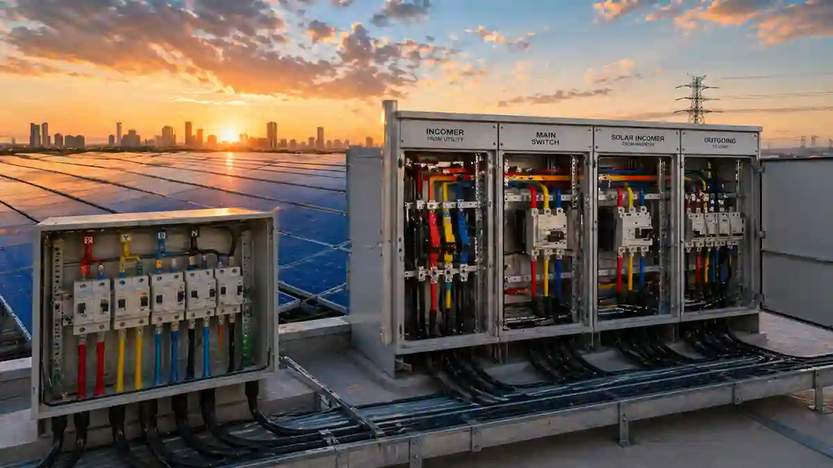
Commercial solar systems connect to the electrical grid at the Point of Common Coupling (PCC) — typically the customer’s main service entrance or a dedicated solar Point of Interconnection (POI) section of the main switchgear. Unlike residential solar, which commonly uses a simple back-fed breaker into the main panel under NEC 705.12(D), commercial solar systems above 100 kW typically use a supply-side connection under NEC 705.12(B) — connecting upstream of the main service disconnect.
The supply-side connection method has several advantages for commercial systems: it avoids the NEC 705.12(D) busbar loading limitation (which would otherwise limit solar backfeed to 120% of busbar rating minus main breaker rating), it allows the solar disconnect to be independent of the main service disconnect, and it is generally preferred by utilities for commercial installations because it provides cleaner protection coordination.
Engineer’s Note: The NEC 705.12(D) 120% rule catches many commercial building owners off guard. If your main switchgear busbar is rated 1,000A and your main breaker is 800A, the maximum solar backfeed breaker under 705.12(D) is only 200A, which limits you to roughly 100 kW at 480V. Supply-side connection under 705.12(B) eliminates this constraint. Make sure your commercial solar installer understands which connection method applies to your system before drawings are finalized.
2. Three-Phase Electrical Design for Commercial Solar
Commercial facilities are served at either 208V three-phase (wye configuration, common in smaller commercial buildings and older construction) or 480V three-phase (delta or wye, standard in industrial and larger commercial facilities). The solar system’s inverter must match the service voltage precisely — this is not adjustable in the field.
| Design Parameter | 208V Three-Phase System | 480V Three-Phase System |
| Maximum practical system size | ~250 kW (conductor sizing becomes prohibitive above this) | Scalable to MW-range |
| Typical commercial application | Smaller offices, retail, older multitenant buildings | Warehouses, manufacturing, institutional, new construction |
| Conductor sizing impact | Higher current for the same kW — larger, more expensive conductors | Lower current — more cost-efficient at scale |
| Transformer requirement | Often none required | May require a step-up transformer to the utility medium voltage |
| Inverter cost premium | ~5–10% more for 208V due to lower volume production | Standard — most commercial inverters are optimized for 480V |
| Protection relay complexity | Moderate — standard over/undervoltage protection | Higher utility often requires directional protection elements |
For systems above 100 kW, 480V is almost always the preferred configuration. The conductor sizing savings alone typically justify specifying a step-up transformer if the facility is served at 208V and the system is large enough to warrant it.
3. IEEE 1547-2018: The Standard That Governs Grid Connection
IEEE 1547-2018 is the primary technical standard governing the interconnection of commercial solar — and all distributed energy resources — to the electric power system. It replaced the 2003 version and significantly expanded requirements in four areas that every commercial solar system must address:
Voltage and Frequency Ride-Through
Commercial solar systems must now ride through (continue operating during) voltage and frequency disturbances that previously would have triggered automatic disconnection. This represents a fundamental shift from the 2003 standard’s ‘trip on any disturbance’ approach. The 2018 standard defines specific voltage and frequency ranges within which the inverter must remain connected and continue generating, with trip thresholds only for excursions beyond defined limits.
This matters for system design because not all inverters support full IEEE 1547-2018 ride-through compliance. Specifying inverters that are UL 1741 SA (Supplement A) certified — the certification that validates IEEE 1547-2018 compliance — is the correct specification requirement.
Reactive Power Capability
Commercial solar systems above 500 kW are now required under IEEE 1547-2018 to provide reactive power support — the ability to inject or absorb reactive power to help the utility manage voltage on the distribution feeder. This requires inverters with active power factor control capability, typically specified as a minimum range of ±0.85 power factor at rated real power output.
Communications Requirements
Systems above 1 MW are required to have a communications interface that allows the utility to monitor and potentially control the system’s operating parameters. Smart inverter communications — using protocols like SunSpec Modbus or IEC 61850 — are now a standard specification requirement for large commercial and utility-scale installations.
Anti-Islanding
Anti-islanding protection — the requirement that a solar system disconnect from the grid within a specified time if the grid loses power — remains a core requirement, now with more precisely defined timing requirements under IEEE 1547-2018 Section 6.5.2. For commercial systems, anti-islanding compliance must be formally tested and documented, not simply assumed from the inverter’s UL listing.
4. The Utility Interconnection Process: What Actually Happens
| Stage | What the Utility Does | What You (or Your Installer) Provide | Typical Duration |
| Application submission | Assigns queue position; begins completeness review | Application form, system specs, single-line diagram, application fee | Day 1 |
| Completeness review | Confirms all required documentation is present | Respond to any completeness deficiency notices promptly | 1–3 weeks |
| Technical screening / Feasibility study | Evaluates impact on feeder voltage, fault current, protection coordination | Inverter specs, IEEE 1547 compliance documentation, protection relay settings | 4–12 weeks |
| P&C study (>500 kW) | Models system impact; specifies required protection relay settings | System electrical model, inverter simulation data | 8–20 weeks additional |
| Interconnection agreement | Drafts legal agreement specifying operating conditions | Review and execute; negotiate terms if appropriate | 2–4 weeks |
| Construction inspection | Utility inspector verifies installation matches approved drawings | As-built drawings, commissioning test results | 1–2 weeks |
| Permission to Operate (PTO) | Final authorization to energize and operate | Anti-islanding test documentation, completed commissioning checklist | 1–2 weeks after inspection |
Field Note: The completeness review stage is where poorly prepared applications die. A utility’s standard for ‘complete’ is strict — a missing attachment, an incorrect form version, or a single-line diagram that does not match the utility’s required format can result in an incomplete determination that resets your queue position to day one. Your installer should have submitted this application to this utility before. If they have not, find someone who has.
5. Protection Relay Requirements for Commercial Solar
For commercial solar systems above 25 kW, utilities typically require the following protection elements, configured to utility-specified setpoints (not default inverter settings):
| Protection Function | IEEE 1547-2018 Reference | Typical Commercial Requirement |
| Overvoltage (OV) | Section 6.4.1 | Trip if voltage exceeds 110% for >1 second; 120% for >0.16 seconds |
| Undervoltage (UV) | Section 6.4.1 | Trip if voltage below 88% for >2 seconds; 50% for >0.16 seconds |
| Over-frequency (OF) | Section 6.5.1 | Trip if frequency exceeds 60.5 Hz for >0.16 seconds |
| Under-frequency (UF) | Section 6.5.1 | Trip if frequency below 57 Hz for >0.16 seconds |
| Anti-islanding | Section 6.5.2 | Disconnect within 2 seconds of island condition; formally tested and documented |
| Directional overcurrent (>500 kW) | Utility-specified, not in IEEE 1547 | 67/67N elements; settings specified in P&C study |
These settings must be programmed into the inverter’s protection relay functions and documented in the commissioning report. Default inverter settings frequently do not match utility-specified values. Protection relay testing — verification that each function trips at the correct setpoint — is a commissioning step that cannot be skipped on commercial installations.
The full commissioning protocol for commercial solar power installations — including protection relay testing, anti-islanding verification, thermal imaging, and performance ratio testing — is covered in the Commercial Solar Panel Installation Engineering Guide.
6. Revenue Metering: What You Need Beyond the Utility Meter
Commercial solar utility interconnection includes a bidirectional revenue meter installed by the utility at the service entrance. This meter records both energy imported from the grid and energy exported to the grid. For most commercial net metering configurations, this single meter determines your billing under the net metering tariff.
However, for commercial systems where production data matters independently of net metering — SREC programs, PPA performance reporting, system performance guarantees, or simply independent verification — a separate production meter at the solar point of interconnection is worth the $1,500 to $4,500 installed cost. A revenue-grade production meter (ANSI Class 0.2 or better) provides auditable production data independent of the utility’s billing meter. It is the difference between trusting that your system is performing as designed and being able to prove it. For the complete financial analysis of commercial solar — including how net metering compensation rates affect system sizing decisions and ROI calculations — see the Commercial Solar Panel Installation guide’s cost and incentive sections.