Master solar panel ground mounting systems. Professional engineering guide to driven piles, helical piers, structural framing, and installation sequencing.
Ground-mounted solar systems account for the majority of utility-scale and commercial solar installations by capacity — and for good reason. They are not constrained by existing building structure; they can be oriented and tilted for maximum energy yield, and they are easier to maintain than rooftop arrays. They are also more complex to engineer correctly, because every element of the support structure must be designed and built where there was nothing before.
If you are still in the decision stage between ground mounting and rooftop, the Ground Mount vs Roof Mount Solar guide provides the comparison framework. This guide picks up where that one ends: once the decision is ground mount, this is the engineering.
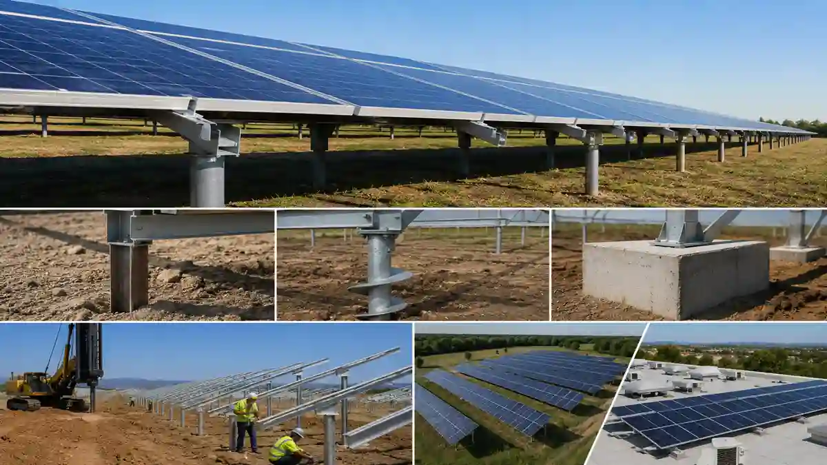
1. Ground Mount Foundation Types
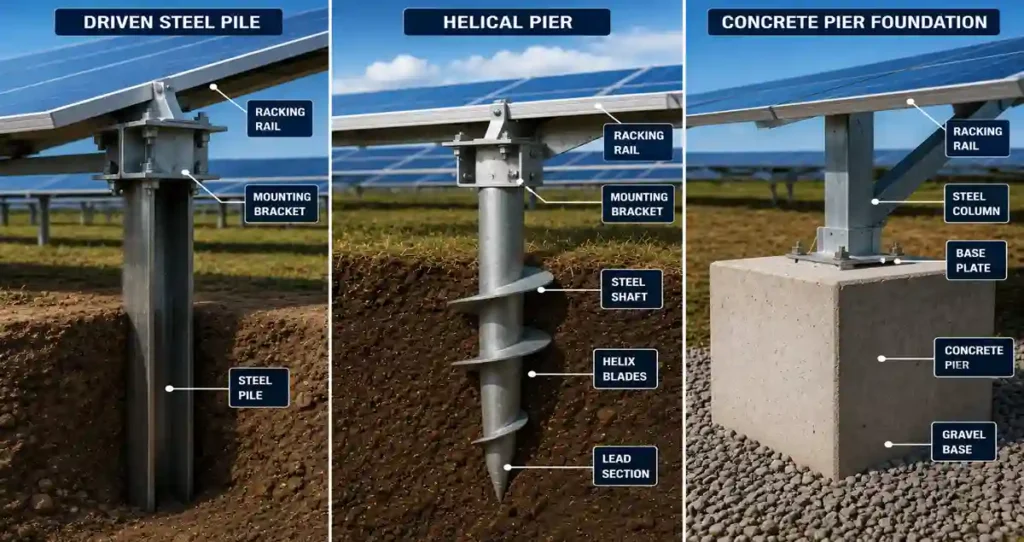
Driven Steel Pile
The most common foundation type for commercial ground-mount solar. Steel wide-flange (W-section) or HSS piles are driven into the ground using a hydraulic impact or vibratory hammer. Driven piles are fast to install — typically 20 to 40 per day — and require no excavation or concrete. Their capacity is determined by soil bearing resistance and pile embedment depth, set by a geotechnical engineer based on a soil investigation.
Helical Pier
Helical piers (screw piles) provide both compressive and tensile (uplift) capacity from the helical bearing plates. They are preferred where driven piles are impractical and where pull-out resistance is a primary design requirement. The wind uplift calculation that determines this requirement is governed by ASCE 7-22 — the same standard that governs rooftop bracket pull-out requirements discussed in the Mounting Brackets for Solar Panels guide.
Concrete Ballast / Pier
Precast concrete ballast blocks or cast-in-place concrete piers are used where ground penetration is not possible — shallow bedrock, utilities in the subgrade, or environmental restrictions on soil disturbance. Concrete foundations are the most expensive option but the most reliable in challenging soil conditions.
2. Ground Mount Structural Frame
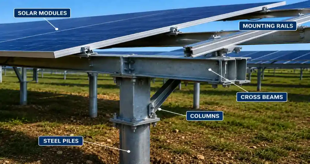
| Structural Component | Typical Material | Engineering Requirement | Common Failure Mode |
| Pile | W6x15 to W8x31 steel; ASTM A36 or A572 | Embedment depth per geotech report; corrosion protection to 6″ below grade | Insufficient embedment; corrosion at soil interface |
| Column | HSS 4×4 or W6 steel; galvanized | Calculated for combined gravity + wind moment at pile connection | Buckling in long unsupported columns; weld failure at base |
| Cross beam | HSS 3×3 or C-channel; galvanized | Designed for rail gravity load + wind; connection to column verified | Deflection under snow load; connection loosening over time |
| Mounting rail | 6061-T6 or 6063-T5 aluminum extrusion | Span between cross beams verified against rail section modulus | Overspan causing rail deflection; module frame cracking |
| Pile-to-column connection | Bolted flange; ASTM F3125 Grade A325 bolts | Moment connection designed for wind overturning | Bolt loosening; insufficient bolt grip length |
The aluminum mounting rail that sits on top of this steel substructure follows the same alloy and span specifications as rooftop rail — covered in the Solar Mounting Rails guide. The module clamps and grounding hardware that attach to that rail are specified in the Solar Panel Mounting Brackets with Hardware guide.
3. Cheapest Ground Mount Solar Racking: What That Phrase Actually Means
The legitimate way to achieve cost-effective ground mount racking is through engineering optimization — calculating the minimum pile embedment required by actual soil conditions, sizing structural members precisely to the wind and snow loads for the specific site, and choosing the foundation type that genuinely fits the soil conditions.
Field Note: I have reviewed proposals for ‘discount’ ground mount racking systems that listed pile embedment depths of 18 inches in a Zone 4 wind area with clay soils. The correct embedment in those conditions, per geotechnical analysis, was 48 to 60 inches. An 18-inch pile in clay soil under wind load is a lever with insufficient resistance at the fulcrum. It will rotate under the first significant wind event. Engineering-optimized cost reduction is legitimate; structural reduction to meet a price point is not.
4. Solar Panel Ground Mounting Systems — Installation Sequence
- Geotechnical investigation: Soil borings at representative locations. Minimum one boring per 50 piles; more in variable soil conditions.
- Layout staking: Pile locations staked per the structural drawing layout. GPS or total station survey for large arrays. Position tolerance typically ±1 inch from design position.
- Foundation installation: Piles driven or screwed to design embedment depth. Pile head elevation set to ±0.25 inch for rail alignment.
- Column and cross beam erection: Steel columns bolted to pile flanges at design torque. Frame geometry verified against design before proceeding.
- Rail installation: Aluminum mounting rails set on cross beams at design spacing. The slip-splice thermal expansion detail explained in the Solar Mounting Rails guide applies identically to ground mount rail installation.
- Module installation: Panels lifted and set on rails, clamped in sequence. Grounding hardware installed at each module.
- Electrical infrastructure: DC home run conduit from combiner boxes to inverter location. The complete commissioning verification follows the checklist in the Solar Panel Rail Mounting Kit installation guide.
5. Ground Mounted Solar System — Performance vs Rooftop
| Performance Factor | Ground Mount (Optimal) | Rooftop (Constrained) | Difference |
| Orientation | True south ± 5° | Determined by roof — often ±30-45° from south | Ground mount advantage: 0-8% more annual energy |
| Tilt angle | Optimized for latitude (typically latitude ± 5°) | Set by roof pitch — may not be optimal | Ground mount advantage: 2-10% more annual energy |
| Shading | Array positioned to avoid shading | HVAC, parapets, adjacent structures — often unavoidable | Ground mount advantage: 0-15% more annual energy |
| Maintenance access | Ground level — zero height hazard, easy cleaning | Roof access — fall protection required | Ground mount advantage |
| System expansion | Additional rows added on adjacent land | Limited by roof area | Ground mount advantage |
For the decision framework comparing ground and rooftop options, see the Ground Mount vs Roof Mount Solar guide. For the full structural engineering context, see the Solar Mounting Systems hub.
6. Frequently Asked Questions (FAQ)
What is the most common foundation type for solar panel ground mounting systems?
The most common foundation type for commercial and utility-scale ground arrays is the driven steel pile (typically W-shape or HSS sections). They are highly cost-effective because they require zero excavation, concrete, or curing time, allowing installation crews to drive 20 to 40 piles per day depending on site soil conditions.
When should helical piers be used instead of driven steel piles?
Helical piers (screw piles) should be specified when soil conditions present low bearing resistance or highly variable profiles where driven piles risk settling. Because of their helical bearing plates, they provide excellent tensile and uplift capacity, making them ideal for high-wind regions governed by ASCE 7-22 wind design parameters.
Can ground-mounted solar arrays be installed on rocky ground or landfill sites?
Yes, but they require concrete ballast blocks or cast-in-place concrete piers instead of driven piles. If a site features shallow bedrock, underground utility cross-overs, or environmental restrictions on subgrade soil disturbance (common in brownfields and landfills), concrete foundations provide a structurally secure, non-penetrating alternative.
How deep do ground mount solar piles need to be embedded?
There is no generic depth; embedment is determined entirely by a site-specific geotechnical investigation. While discount configurations sometimes unsafely skimp on depth, a rigorous engineering design in standard clay soils or high-wind zones typically requires an embedment depth of 48 to 60 inches (4 to 5 feet) to safely resist overturning forces.
What causes structural mechanical failure in ground-mounted solar racking?
The most common failure modes include overspanning aluminum rails beyond their calculated section modulus (causing rail deflection and module cracking), bolt loosening at the pile-to-column moment connection due to improper installation torque, and accelerated galvanic or chemical corrosion at the soil-to-steel interface if inadequate zinc coating/galvanization was applied.
Related guides on SolarVisionAI.com
Solar Panel Installation: Complete Engineering Guide (2026)
Solar Panel Installation Cost: The Complete 2026 Breakdown
Commercial Solar Panel Installation: Engineering Guide 2026
When Is the Best Time to Install Solar Panels?
Solar Power System in 2026: Types, Cost, ROI & AI Optimization