Solar mounting rails — alloy selection, T-slot geometry, span tables, thermal expansion design, and attachment spacing for US commercial and residential solar installations.
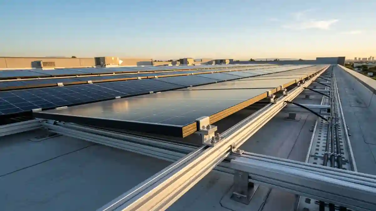
The mounting rail is the structural backbone of a solar panel array. Every solar panel in a rail-based mounting system sits on it, clamps to it, and transfers its load through it. The rail spans between attachment points, resists the bending forces from gravity and wind, and provides the T-slot channel that accepts the mid and end clamps holding each module in place.
Rail selection is an engineering decision that affects every downstream element of the mounting system. It connects directly to the bracket specification in the Solar Panel Mounting Brackets guide — because the rail and bracket must be from the same engineering system to maintain tested load ratings — and to the full structural framework in the Solar Mounting Systems hub.
1. Rail Profile and T-Slot Geometry
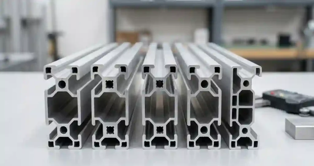
Commercial solar mounting rails are extruded aluminum profiles with a T-slot channel on the top surface. The T-slot dimensions are not universal — different manufacturers use different slot widths and depths, which determines clamp compatibility. A bolt head from a different manufacturer’s clamp will either not fit or fit loosely, creating an unreliable connection.
The most important consequence of T-slot geometry variation is that rails and clamps from different manufacturers are generally not interchangeable. The complete clamp specification — mid clamp, end clamp, clamping range, and grounding hardware compatibility — is covered in the Solar Panel Mounting Brackets with Hardware guide.
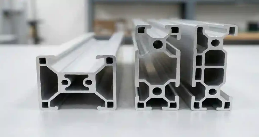
2. Rail Sizes and Structural Capacity
| Rail Profile | Weight (lbs/ft) | Moment of Inertia (in4) | Typical Max Span | Application |
| Light rail (40mm height) | 0.55-0.70 | 0.08-0.12 | 36-48 inches | Residential; low-wind zones; short spans |
| Standard rail (50mm height) | 0.75-0.95 | 0.15-0.22 | 48-60 inches | Light commercial; most residential; moderate wind |
| Heavy rail (70-80mm height) | 1.10-1.45 | 0.35-0.55 | 60-84 inches | Commercial rooftop; high-wind zones; long spans |
| Commercial C-channel | 1.20-1.80 | 0.50-0.90 | 72-96 inches | Ground mount cross beams; heavy commercial |
| Double rail / wide rail | 1.50-2.20 | 0.60-1.20 | 84-120 inches | Large-format modules; high-load applications |
Maximum span is not a single number — it depends on the loading condition. A rail that spans 60 inches safely under standard residential loading may be limited to 48 inches under a high-wind commercial load calculation. Always verify span against the manufacturer’s load table for your specific wind speed and snow load zone.
3. Rail Alloy Specification
6063-T5 Aluminum
The standard alloy for solar mounting rail extrusions. Yield strength of 21 ksi (145 MPa). Extrudes cleanly into the T-slot profile with tight dimensional tolerances. Adequate for most residential and light commercial solar installation applications in standard wind and snow load zones.
6061-T6 Aluminum
Higher-strength alloy with yield strength of 40 ksi (276 MPa) — nearly double that of 6063-T5. Specified for commercial applications in high-wind zones (design wind speed above 115 mph), long-span conditions (rail spans above 72 inches), or applications with combined high wind and snow load.
Engineer’s Note: The alloy designation should appear on the product specification sheet or mill certificate. If a vendor cannot provide the alloy designation in writing, the product should not be accepted for a commercial installation. The same 6061-T6 vs 6063-T5 distinction applies to the aluminum rails used in ground mount structural frames — discussed in the Solar Panel Ground Mounting Systems guide (Post 6).
4. Solar Panel Roof Mounting Rails — Roof-Specific Requirements
Thermal Expansion
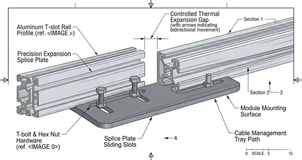
Aluminum expands at approximately 13 × 10⁻⁶ inches per inch per °F. A 20-foot rail section in a climate with a 120°F temperature range will expand and contract by approximately 0.37 inches over its length. If both ends of the rail are rigidly fixed, this thermal movement creates compressive stress in summer and tensile stress in winter — cycled 365 times per year for 25 years.
The correct design accommodates thermal expansion by allowing one end of each rail splice to slide freely. At the slip end, the splice connector is torqued to approximately 50% of the full specification — enough to transfer shear loads but not prevent axial movement. This detail is frequently omitted from budget installations and creates cracked rail sections or pulled bracket fasteners within 3 to 5 years.
Attachment Spacing
Rail attachment spacing to the roof must be calculated for the specific loading conditions at that site. Edge and corner attachments in high-wind arrays frequently require 50 to 75% of the standard interior spacing. The bracket pull-out capacity requirements that drive this spacing are covered in the Mounting Brackets for Solar Panels guide. The roof-type-specific bracket installation details are in the Roof Solar Panel Mounting Brackets post.
5. Installation Verification Checklist
- Rail alloy confirmed as specified (6063-T5 or 6061-T6 per design)
- Rail profile compatible with specified module clamps — slot width verified
- Splice connector slip joints installed at correct end of each rail splice — not over-torqued
- Attachment spacing verified against load table for site wind and snow zone
- Rail end caps installed at all exposed rail ends — prevents bird and insect nesting
- Rail splices located between modules — not under module clamps
- Rail level within ±3mm across array width — verified with level or laser
6. The Rails Cluster — Navigation
- Post 9: Rail Mounted Solar Panels — How the System Works & What to Buy
- Post 10: Solar Panel Rail Mounting Kit — Complete Installation Guide
For the full mounting system context, see the Solar Mounting Systems hub.
Frequently Asked Questions (FAQ)
What is a solar mounting rail?
A solar mounting rail is an aluminum structural member that supports solar panels, transfers loads to the mounting brackets, and provides attachment points for module clamps and grounding hardware.
What is the difference between 6063-T5 and 6061-T6 solar rails?
6063-T5 is the most common alloy used in residential and light commercial solar installations, while 6061-T6 provides significantly higher strength and is preferred for long-span and high-wind applications.
Are solar mounting rails universal?
No. Solar mounting rails are not universally compatible because T-slot dimensions vary between manufacturers. Rail systems should be used with approved clamps and hardware from the same engineering system.
How far can solar mounting rails span between attachment points?
The allowable span depends on rail profile, alloy, wind load, snow load, and manufacturer load tables. Typical spans range from 36 inches for light rails to over 96 inches for heavy commercial profiles.
Why is thermal expansion important in solar mounting rails?
Aluminum rails expand and contract with temperature changes. Properly designed slip joints and expansion details prevent rail buckling, bracket pull-out, and long-term structural damage.
Related guides on SolarVisionAI.com
Solar Panel Installation: Complete Engineering Guide (2026)
Solar Panel Installation Cost: The Complete 2026 Breakdown
Commercial Solar Panel Installation: Engineering Guide 2026
When Is the Best Time to Install Solar Panels?
Solar Power System in 2026: Types, Cost, ROI & AI Optimization