Rail mounted solar panels — two-stage load path explained, layout principles, component evaluation checklist, NEC 690 code compliance, and electrical wiring integration guide.
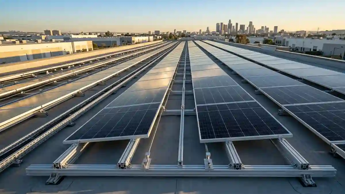
Rail mounting is the dominant configuration for commercial and residential solar installations. Walk up to almost any commercial rooftop solar array in the US and you will find aluminum rails running horizontally or along the slope, panel frames clamped to those rails, and the rails attached to the roof through brackets at regular intervals. The system is not complicated in concept. The engineering that makes it work reliably for 25 years is.
This guide covers how rail-mounted solar panel systems actually work — mechanically, structurally, and electrically. For the complete rail specification — alloy, profile, span tables, and T-slot geometry — see the Solar Mounting Rails guide. For the step-by-step installation sequence, kit verification, and commissioning checklist, see the Solar Panel Rail Mounting Kit guide.
1. How a Rail Mounted Solar Panel System Works

The structural logic is a two-stage load path. Stage one: the panel frame transfers gravity and wind loads to the mounting rail through the mid and end clamps. Stage two: the rail transfers those accumulated loads to the roof structure through the bracket attachment points.
Each stage has engineering requirements. The pull-out capacity requirements — by bracket type and substrate — are covered in the Mounting Brackets for Solar Panels guide. The complete load path — from panel frame through clamp through rail through bracket through substrate — must be engineered as a system.
2. Rail Mount Solar Panel — Layout Principles
- Rail orientation: Rails run parallel to the roof eave (horizontal) on most pitched roof installations. The thermal expansion and slip-splice detail that makes this work over 25 years is explained in the Solar Mounting Rails guide.
- Rail rows per module: Standard modules are clamped to two rails — one near the top edge and one near the bottom edge of the module. The exact rail position is specified by the module manufacturer (typically within the middle 60% of the module height). Rail position outside the manufacturer’s specified range voids the module’s structural warranty.
- Rail overhang: Rail sections should not overhang beyond the last attachment point by more than 40% of the attachment spacing. Excessive overhang creates a lever arm that amplifies loads at the last bracket and can cause the rail end to lift under wind uplift.
- Splice location: Splice connectors between rail sections should be located between modules — not under module clamps. A splice under a clamp creates a stress concentration and can cause clamp loosening as the splice settles under load.
3. Rail Mount Solar Panel — System Components to Evaluate
| Component | What to Verify | Red Flags |
| Rail | Alloy grade (6063-T5 or 6061-T6); moment of inertia for specified span; T-slot dimensions | No alloy specification; generic ‘aluminum’ without grade |
| Mid clamps | Clamping range compatible with module frame height; torque specification provided; UL 2703 listed | No clamping range specification; no torque spec; unlisted product |
| End clamps | Profile matches module frame edge; end cap included; grounding bonding method specified | Missing end cap; no bonding hardware |
| Splice connectors | Slip joint design for thermal expansion; shear capacity meets design requirement | Rigid splice only (no slip joint); no capacity data |
| Brackets / roof hooks | Pull-out capacity for site-specific substrate; flashing assembly compatible with roof type | No pull-out test data; generic flashing not roof-type specific |
| Fasteners | Grade 316 stainless throughout; torque specification for each fastener size | Zinc plated; 304 stainless; no torque specification |
The complete hardware submittal checklist is in the Solar Panel Mounting Brackets with Hardware guide. For roof-type-specific bracket requirements, see the Roof Solar Panel Mounting Brackets post.
4. Solar Panel Rail Mount — Electrical Wiring Integration

The mounting rail is not just a structural element — it is the cable management backbone of the DC wiring system. DC cable management must keep cables organized, protected from UV exposure and mechanical damage, and routed to minimize resistance losses in the DC home runs. Cables should be secured every 12 to 18 inches to prevent sagging and vibration fatigue at connector pins.
5. Solar Panel Rail Mounting — Code Compliance Points
- NEC 690.12: Rapid shutdown — the rail-mounted system must be compatible with the rapid shutdown device (if required by local adoption of NEC 2017 or later) at the roof penetration or array boundary.
- NEC 690.43: Equipment grounding — all module frames and mounting system metal must be bonded to the equipment grounding conductor. The bonding method must be UL 2703 listed.
- NEC 690.31(G): Cable management — DC conductors on or in buildings must be in conduit or listed raceway from the point they leave the array.
- ASCE 7-22: Structural loads — the rail attachment spacing and bracket pull-out capacity must be documented in the structural drawings as meeting the calculated wind uplift and gravity loads for the specific site.
For the complete structural engineering framework, see the Solar Mounting Systems hub. For the full installation process, continue to the Solar Panel Rail Mounting Kit guide.
Frequently Asked Questions (FAQ)
What are rail mounted solar panels?
Rail mounted solar panels are photovoltaic modules attached to aluminum mounting rails using mid clamps and end clamps. The rails transfer structural loads to roof brackets or ground-mount support structures.
Are rail mounted solar panels better than rail-less systems?
Rail mounted systems generally provide greater structural flexibility, easier module alignment, improved cable management, and broader compatibility with different solar panel sizes and roof types.
How many rails are required for a solar panel?
Most standard solar panels are mounted using two horizontal rails positioned within the manufacturer’s approved clamping zones. Some large-format modules may require additional support depending on loading conditions.
What material is used for solar mounting rails?
Most solar mounting rails are manufactured from 6063-T5 aluminum alloy, while higher-strength 6061-T6 aluminum is often specified for commercial projects, long spans, and high-wind applications.
How are electrical cables managed in rail mounted solar systems?
Solar mounting rails often serve as the cable management backbone of the array. Cables are secured using clips or ties and routed to minimize UV exposure, vibration damage, and electrical losses.
Related guides on SolarVisionAI.com
Solar Fence Post Lights: Cap Sizes, Types & Install Guide
Solar Lights for Vinyl, Aluminum & Wood Fence Posts