Solar powered flood lights with motion sensor explained — PIR vs radar detection, beam angle geometry, zone overlap planning, and smart scheduling for winter battery reliability.
A technical guide to solar powered flood lights with motion sensors — covering PIR and radar detection methods, beam angle geometry, zone overlap planning for perimeter coverage, remote control operation, and smart scheduling that extends winter battery life. Written by a Registered Professional Engineer
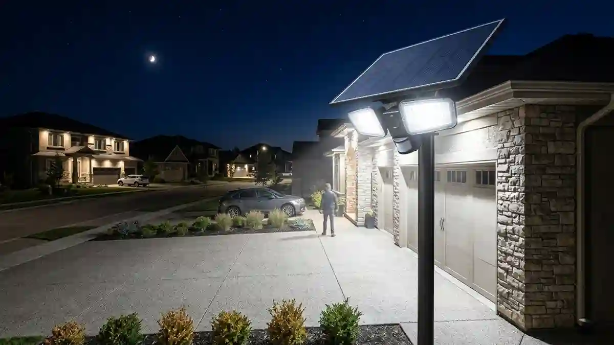
The motion sensor is the component that makes a solar flood light practical rather than just a high-drain battery load that runs flat every night. Without motion triggering, a 3000-lumen flood light running continuously would exhaust most solar panels‘ battery reserves in 3–4 hours. With motion triggering, the same unit can cover an entire night at standby draw, activating to full output only when needed.
But motion sensors in flood lights are not all equivalent. Detection range, angle geometry, sensor type, and how the unit manages the transition between standby and full output all affect whether the light actually covers the area you intend — and whether it triggers when it should and stays quiet when it shouldn’t.
For the full flood light sizing context, the solar flood lights guide covers lumen output, IP ratings, and panel sizing in detail.
1. How Motion Sensors Work in Solar Flood Lights
Most solar flood lights use a Passive Infrared (PIR) sensor as the motion detection element. The PIR detects changes in infrared radiation within its detection cone — specifically, the thermal signature of a warm body moving through the sensor’s field of view.
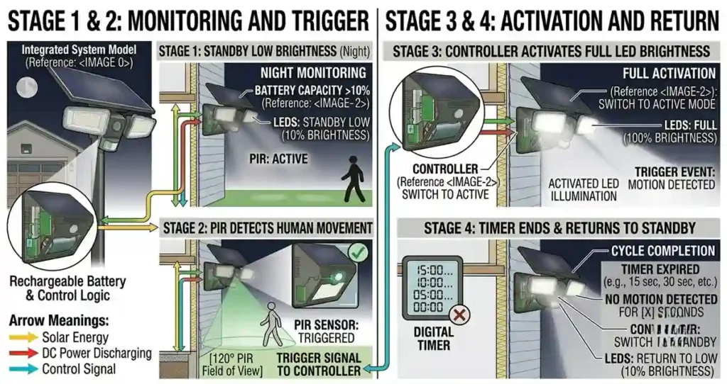
The operating cycle in a motion-triggered solar flood light:
Standby: LED operates at low output (5–20% of rated) or off, PIR sensor active at minimal power draw (~1–2mA)
Trigger: PIR detects motion → controller signals LED driver to ramp to full output → flood area illuminated
Hold: Light remains at full output for the set hold time (typically 20–120 seconds, adjustable)
Return: After hold time, LED ramps back to standby level — PIR remains active
The energy saving from this cycle is substantial. A 3000-lumen unit drawing 30W at full output but only triggering 15 times per night at 60 seconds per trigger uses 7.5Wh for triggered events plus standby draw — compared to 150Wh for continuous operation. Motion triggering extends practical battery runtime by a factor of 5–10 in typical residential applications.
Engineer’s Note: The ramp speed from standby to full output matters in security applications. A unit that takes 2–3 seconds to reach full brightness after trigger may miss the first few seconds of a detected event in darkness — the intruder has already passed through the illuminated zone before full output is reached. Look for units specifying <0.5 second ramp time for security applications.
2. Motion Sensor Types: PIR, Radar, and Dual
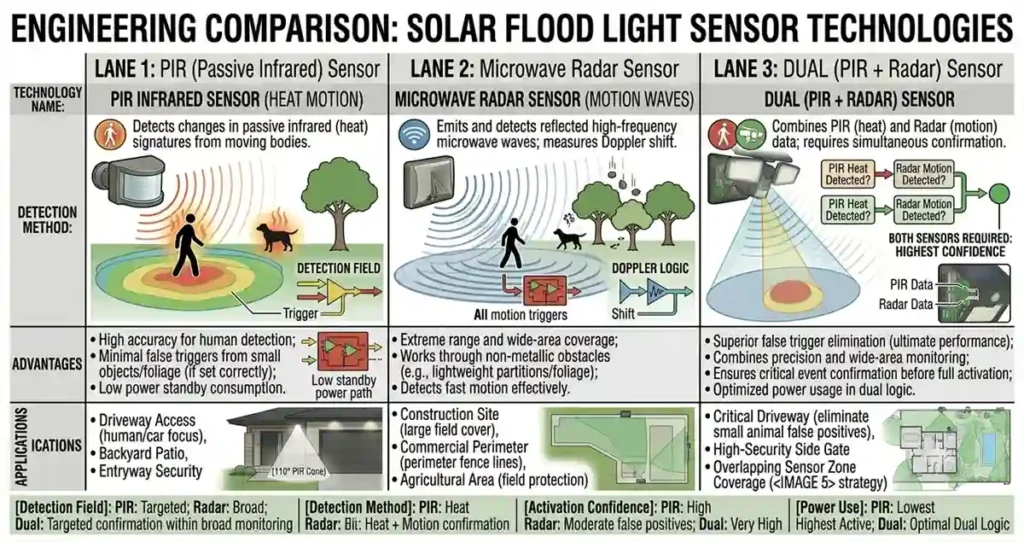
| Sensor Type | Detection Method | False Trigger Rate | Power Draw | Best Application |
| PIR (standard) | Infrared heat differential | Medium | Very low (~1mA standby) | Residential — all applications |
| Microwave (radar) | Doppler frequency shift | Low | Medium (~10–30mA) | Through-wall detection needed |
| Dual PIR+radar | Both required to trigger | Very low | Medium | High-false-trigger environments |
| Camera AI | Video frame classification | Very low | High (~100–300mA) | Where object ID matters |
| Acoustic | Sound detection | High | Low | Rarely used — supplementary only |
For most residential solar flood light applications, standard PIR is the correct choice. It draws minimal standby power — critical for battery-powered solar applications — and provides adequate detection for all standard residential perimeter scenarios.
Radar (microwave) sensors are worth considering in specific cases: environments with temperature extremes that reduce PIR thermal contrast, or applications where through-barrier detection is needed (detecting motion behind a gate or thin wall). The higher standby power draw is the main tradeoff for solar applications.
Dual PIR+radar sensors reduce false trigger rate significantly — both sensors must trigger simultaneously for the light to activate. This is useful in environments with high false trigger frequency: near roads, in windy areas with vegetation, or near HVAC equipment.
3. Detection Angle Geometry: The Engineering Detail
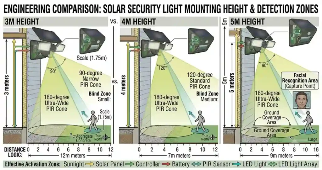
Detection angle is where most solar flood light specifications are misleading. The listed angle is the sensor’s nominal field of view — but how that field of view projects onto the ground plane at your mounting height is what actually determines coverage area.
| Detection Angle | Max Width at 10m | Blind Zone at Base | Overlap Spacing | Best For |
| 90° | ~7m | Minimal | 5–6m between fixtures | Narrow corridor, pathway |
| 120° | ~10m | Small — tilt sensor down | 6–8m between fixtures | Standard residential |
| 180° | ~14m | Moderate — mount higher | 10–12m between fixtures | Wide area, commercial |
| 270°+ | Full surround | Requires elevated mount | Single unit corner coverage | Corner posts, isolated structures |
The Blind Zone Problem
Every PIR sensor mounted above ground level has a blind zone directly beneath the mounting point — the area the detection cone doesn’t reach because the cone angle doesn’t extend that far downward. The size of the blind zone increases with mounting height.
At 3m mounting height with a 120° detection angle and 15° downward tilt: blind zone radius approximately 0.8–1m below the fixture.
At 5m mounting height with the same geometry: blind zone radius approximately 2–3m below the fixture.
For building entry applications where coverage directly below the fixture matters, address the blind zone by either mounting lower, adding a second lower fixture, or choosing a unit with a wider vertical detection angle.
Engineer’s Note: The vertical detection angle is rarely published in solar flood light specifications but matters significantly for high mounting applications. A sensor with a 60° vertical angle at 5m mounting height covers from approximately 2.9m out from the base to maximum range — leaving a 2.9m radius blind zone below. A sensor with a 90° vertical angle at the same height reduces that blind zone to approximately 1m radius. If mounting above 4m, request the vertical detection angle specification.
4. Zone Planning for Complete Perimeter Coverage
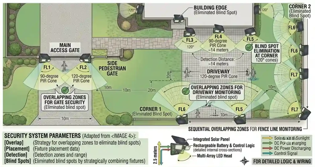
A single solar flood light rarely covers an entire perimeter without blind spots. Planning for overlapping detection zones is the engineering approach to complete coverage.
Step 1: Map the perimeter
Identify all entry points, corners, and areas of concern. Mark the positions where coverage is critical — entry doors, gate openings, vehicle access points — versus areas where secondary coverage is acceptable.
Step 2: Determine mounting positions
Position fixtures so detection zones overlap by 1–2m between adjacent units. Apply the 70–80% real-world factor to listed detection range when planning. A fixture listed at 12m detection range reliably covers 9–10m.
Step 3: Address corners explicitly
Corners require dedicated fixtures with the detection zone aimed into the blind area behind the corner. A fixture mounted on the building facing the corner perimeter cannot cover the area behind the corner — a second fixture on the adjacent face is required.
Step 4: Test and adjust after installation
Walk the entire perimeter after installation and identify any zones that don’t trigger detection. Adjust PIR tilt angle, sensitivity, and fixture position before finalising. Most adjustments can be made from ground level if the fixture has a remote control — which brings us to the next section.
Field Note: On a perimeter installation with four flood lights covering a 40×20m yard, the original placement had two blind zones — one behind a corner structure and one in a depression in the terrain that reduced sensor line-of-sight. Both were identified in the post-installation walk test. One fixture was repositioned; one PIR tilt angle was adjusted. Total adjustment time: 25 minutes. The result was complete perimeter coverage with no blind zones. The walk test is not optional — it’s the commissioning step that validates the design.
5. Remote Control Operation: Practical Engineering
Solar powered flood lights with remote control allow adjustment of brightness, PIR sensitivity, hold time, and operating mode without accessing the mounted fixture. For flood lights mounted at 4–5m height, this is a significant practical advantage over fixed-setting units.
Key adjustable parameters via remote:
Brightness level: typically 3–5 preset levels (30%, 50%, 70%, 100%). Running at 70% output extends battery runtime by approximately 30% with minimal visible light reduction.
PIR sensitivity: adjusting sensitivity controls detection range. High sensitivity extends range but increases false trigger rate. Medium sensitivity is the practical default for most applications.
Hold time: the duration the light stays at full output after trigger. Longer hold times (60–120 seconds) suit security applications. Shorter hold times (20–30 seconds) extend battery life for high-traffic applications where frequent short triggers would otherwise drain the battery.
Operating mode: motion-only, dim-plus-motion (standby at 20%, full on trigger), or full-time at set brightness. Motion-only is the most battery-efficient; full-time is available for applications that need sustained illumination regardless of activity.
6. Smart Scheduling for Winter Battery Management
This is where solar flood lights with intelligent controllers offer a genuine advantage over fixed-mode units. Smart scheduling adjusts operating parameters based on battery state and time of night — delivering higher output when battery is full (early evening) and automatically reducing output or sensitivity as the battery depletes through the night.
In practical terms: a smart flood light at 11 PM with a full battery runs at 100% output with high PIR sensitivity. At 3 AM with 40% battery remaining, the same unit automatically drops to 60% output and medium PIR sensitivity — maintaining basic security coverage while ensuring the battery doesn’t fully discharge before dawn.
This adaptive behaviour is not AI in a machine-learning sense — it’s rule-based power management. But it’s effective and makes a measurable difference in winter reliability where charge capacity is reduced. It’s one area where solar flood lights with intelligent controllers are genuinely better than simple on/off motion-triggered units.
Engineer’s Note: When evaluating solar flood lights with smart scheduling, look for units that publish their battery management algorithm — specifically, at what battery voltage or state-of-charge the unit transitions between operating modes. A unit that transitions at 50% SOC preserves more battery margin than one that runs at full output until 20% SOC and then shuts off abruptly. The former gives you predictable reduced performance; the latter gives you unexpected failure.
Frequently Asked Questions
How do I stop my solar flood light from false triggering?
Four steps: (1) Reduce PIR sensitivity via the remote or adjustment dial. (2) Angle the PIR away from roads, HVAC equipment, and moving vegetation. (3) If available, switch to dual PIR+radar mode, which requires both sensors to trigger simultaneously. (4) Adjust the detection zone angle — a slightly upward tilt reduces ground-level sensitivity to animals and blowing debris. If false triggers persist after these adjustments, the PIR sensor itself may be defective.
What is the best hold time setting for a solar flood light?
For security applications: 60 seconds. This provides enough illumination time to capture a full event while not draining the battery on frequent triggers. For driveway or entry lighting where the trigger is expected (returning vehicle, regular foot traffic): 20–30 seconds is sufficient and more battery-efficient. For agricultural or perimeter applications with infrequent triggers: 120 seconds allows time to investigate before the light extinguishes.
Can solar flood lights with motion sensors be set to stay on all night?
Yes, most units include a continuous operation mode. However, the battery capacity of most self-contained solar flood lights is insufficient to sustain high lumen output all night continuously — 3000 lumens for 8 hours requires approximately 200Wh of storage, which exceeds the capacity of most integrated units. Continuous operation at full output is practical only with units that have separate large-capacity battery storage. At reduced output (30–50%), continuous all-night operation is achievable with most mid-range units.
How far should solar flood lights be spaced for full perimeter coverage?
At 3m mounting height, space fixtures 6–8m apart for overlapping coverage with a 120° detection angle. At 4m mounting height, 8–10m spacing. Apply the 70–80% factor to listed detection range when planning. For corner coverage, position dedicated fixtures aimed into the corner blind area — do not rely on adjacent perimeter fixtures to cover corners.
Final Thoughts
Motion sensor geometry is the factor that determines whether a solar flood light installation works as intended. The lumen output and IP rating are important, but a well-specified unit in the wrong position — wrong mounting height, wrong PIR tilt angle, wrong detection zone orientation — will miss the events it’s supposed to detect.
Plan the detection zone coverage before mounting. Walk test after installation. Adjust. The extra 30 minutes of commissioning is the difference between an installation that works and one that has persistent blind spots.
For the commercial-scale application of these principles, the commercial solar flood lights guide covers larger installations where wattage, mounting engineering, and grid-tie options become relevant.
Related guides on SolarVisionAI.com
Solar Motion Sensor Flood Light: IP Ratings & Sizing Guide — solarvisionai.com/solar-flood-lights/
Solar Security Lights: What Actually Works — solarvisionai.com/solar-security-lights/
LED Solar Security Lights — solarvisionai.com/led-solar-security-lights/