
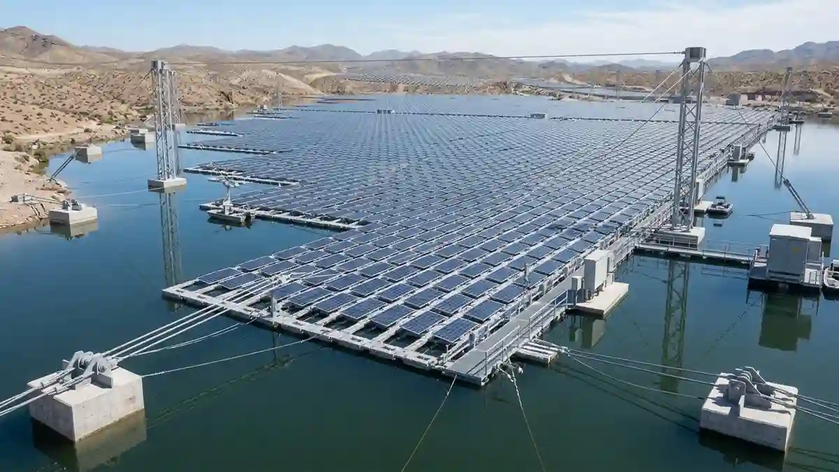
Floating solar mounting system engineering — HDPE pontoon design, mooring systems, buoyancy calculations, wave and wind loading, US reservoir and canal applications.
A floating solar mounting system does everything a ground mount does — it supports solar panels, maintains their orientation, resists wind and environmental loads, and provides a platform for electrical connections — but it does all of this while floating on water. The structural engineering principles involved are borrowed from three different disciplines: solar mounting engineering, marine platform design, and mooring system engineering. The combination produces a system type that is unlike any other solar installation in its design requirements, failure modes, and site-specific engineering demands.
The global floating solar market reached $7.8 billion in 2025 and is growing at approximately 16% annually. In the United States, the driver is straightforward: available flat land in high-solar-resource regions is increasingly constrained, water bodies are abundant, and the secondary benefit of reduced water evaporation from reservoirs and irrigation infrastructure has made floating solar a priority in water-stressed western states. California, Arizona, Colorado, and Texas all have active floating solar projects on reservoirs, wastewater treatment ponds, and irrigation canals.
This guide covers the structural and engineering requirements for floating solar mounting systems — what they consist of, how they are designed, where they are the right choice, and what the US regulatory and permitting landscape looks like for water-body solar installations. For land-based mounting alternatives on challenging terrain, see the Tensile Solar Mounting Systems guide. For the complete solar mounting system taxonomy, see the Solar Mounting Systems hub.
1. What a Floating Solar Mounting System Consists Of
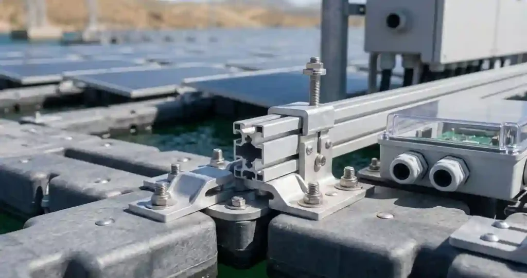
A floating solar mounting system has five primary components that do not exist in any land-based solar installation: the floating platform, the mooring system, the inter-module connection system, the water-rated electrical infrastructure, and the shore connection.
Floating Platform
The floating platform is the structural foundation of the entire system — the equivalent of the ground and foundation system in a conventional installation. Platforms are almost universally made from high-density polyethylene (HDPE) — a buoyant, UV-resistant, chemically inert polymer that does not corrode in water, does not leach chemicals into the water body, and can be formed into modular interlocking pontoon units that snap together to form arrays of any size.
HDPE pontoon modules are typically 1 to 3 meters in size, rated for a specific buoyancy load (the weight of panels, structure, and personnel they can support without submerging), and designed to interlock mechanically without fasteners — which simplifies installation and allows reconfiguration. The pontoon material specification matters: UV resistance must be verified for the specific geographic location and solar irradiance level. Pontoons that are not UV-stabilized for high-irradiance environments degrade within 5 to 10 years.
Mooring System
The mooring system holds the floating array in position on the water body — preventing it from drifting with wind and current, while allowing the platform to rise and fall with water level changes. This is the most site-specific element of a floating solar installation and the one most likely to be underengineered on budget projects.
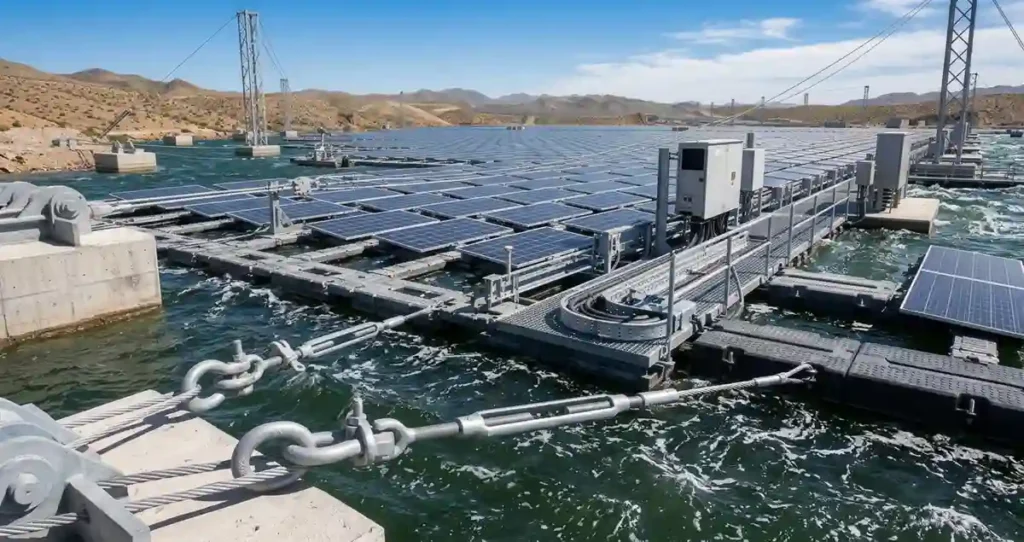
Mooring configurations for floating solar include:
- Anchor and chain mooring: Concrete or steel anchors placed on the water body bed, with galvanized or stainless steel chains connecting anchor to platform. The most common configuration for enclosed water bodies (reservoirs, ponds, lakes) with stable bed conditions.
- Pile mooring: Steel or concrete piles driven or cast into the water body bed, with the floating platform guided along the piles as water level changes. Used where anchor holding capacity is limited or where precise lateral position control is required.
- Shore anchor mooring: Steel cables connecting the floating platform to anchors on the shore or bank. Used for smaller installations and canal-top solar where shoreline access is available at both sides of the array.
- Hybrid mooring: Combination of anchor points in the water body bed and shore connection cables. Most common for large reservoir installations where the combination of offshore anchors and shore cables provides the most reliable position control.
Inter-Module Connection System
Individual pontoon modules carrying solar panels must be connected to each other in a way that transmits structural loads across the array while accommodating the relative movement between modules as wave action, wind, and uneven loading cause the platform to flex. Rigid connections between modules would crack under the cyclic loading from wave action. The inter-module connection system must be flexible enough to allow controlled relative movement while strong enough to keep the array intact under storm conditions.
Most commercial floating solar systems use flexible HDPE connectors — short sections of the same polymer as the pontoon material — that allow limited relative rotation between modules while maintaining the structural integrity of the array perimeter. The design requirement for inter-module connectors is a fatigue life that exceeds the design storm cycle count over the system’s 25-year life.
Water-Rated Electrical Infrastructure
All electrical components on a floating solar system operate in a high-humidity, splash-prone, and potentially submersion-risk environment. Standard solar electrical components — string combiners, junction boxes, conduit fittings — are not adequate for floating solar applications. Water-rated electrical infrastructure requires:
- All junction boxes and combiners rated to IP68 — fully submersible to 1 meter for 30 minutes minimum
- DC cables rated for continuous wet-location exposure — USE-2 or PV wire with water-resistant jacket
- MC4 connectors rated for continuous submersion — standard MC4 connectors are splash-resistant but not submersion-rated
- Cable management that accommodates platform flexure — cables secured at intervals short enough to prevent fatigue from cyclic bending as the platform moves
- Inverter location on shore or on a dedicated floating equipment platform elevated above the waterline — inverters are not water-rated and must be protected from splash and flood
Shore Connection
The electrical connection from the floating array to the shore — the equivalent of the DC home run in a ground-mount system — must cross the water body shoreline in a way that accommodates water level variation and platform movement. Typical shore connection methods include: submarine cable laid on the water body bed (used for fixed-level water bodies), festooned cable with slack loops that accommodate water level variation (used for reservoirs with significant seasonal level change), and flexible armored cable in a floating conduit that rises and falls with the platform.
2. Floating Solar Mounting System — Structural Engineering
Buoyancy Calculation
The fundamental structural calculation for a floating solar power system is the buoyancy check — verifying that the floating platform can support the design load (panels, structure, ballast if any, and maintenance personnel) without submerging to a depth that risks water ingress to electrical components or structural instability.
Buoyancy is governed by Archimedes’ principle: the buoyant force equals the weight of water displaced by the submerged volume of the platform. For a modular HDPE pontoon system, the design calculation must account for:
- The dead load of the complete array (panels + racking + pontoons + cable management) per unit area
- The live load of maintenance personnel — typically 250 lbs per person, with a minimum of two simultaneous locations
- The freeboard requirement — the minimum acceptable elevation of the platform above the waterline, which determines the water volume available for displacement before electrical components are at risk
- The buoyancy reduction from damaged or flooded pontoon modules — a minimum redundancy of 15 to 20% additional buoyancy above the calculated requirement is standard engineering practice
Wave and Wind Load Engineering
Floating solar platforms experience dynamic loading from wind and wave action that has no equivalent in land-based solar engineering. Wind loads on the panel array are calculated using ASCE 7-22 methods similar to ground-mount systems. Wave loads on the platform are calculated using hydrodynamic methods that depend on the wave height, period, and direction — which are determined by the fetch length (the distance over which wind can generate waves) and wind speed at the specific water body.
For enclosed water bodies — reservoirs, ponds, and lakes — wave heights are typically modest: 0.3 to 1.5 meters for most US inland water bodies. For large lakes and reservoirs with significant fetch (Great Lakes, large western reservoirs), wave heights can reach 2 to 3 meters under storm conditions, which requires more robust platform and mooring design.
Engineer’s Note: The wave load calculation is the element of floating solar engineering that is most frequently underestimated on projects I have reviewed. Engineers who are experienced in land-based solar but new to floating systems tend to treat wave load as a minor add-on to the wind load calculation. On a reservoir with a 2-mile fetch and a 50-year storm wind speed of 80 mph, the wave-induced platform acceleration can be 0.3 to 0.5g — an order of magnitude larger than the dynamic load from wind on a land-based system. The mooring and inter-module connection design must be developed for the actual hydrodynamic environment, not estimated from analogous land-based experience.
Mooring Load Calculation
The mooring system must resist the combined force of wind drag on the panel array, current drag on the submerged platform, and wave forces — in the worst-case combination that can occur at the specific site. Mooring load calculation requires:
- Wind drag calculation: wind load on the panel array projected area at the design wind speed, in the worst-case direction (typically perpendicular to the array long axis)
- Current drag calculation: current force on the submerged platform area at the design current speed — typically determined from historical flow data for the water body
- Wave force calculation: hydrodynamic force on the platform from the design wave at the mooring attachment points
- Mooring line tension: the vector sum of wind, current, and wave forces distributed to the mooring lines based on their geometry and stiffness
- Anchor holding capacity: the anchor must resist the mooring line tension plus a safety factor of 2.0 to 3.0 depending on consequence of anchor failure and water body type
3. Floating Solar Mounting System — Platform Types
| Platform Type | Material | Buoyancy Mechanism | Best Application | US Market Availability |
| Modular HDPE pontoon | High-density polyethylene | Closed-cell foam or sealed air chambers in HDPE modules | Reservoirs, ponds, wastewater ponds — most US applications | Multiple US suppliers — most mature technology |
| Concrete pontoon | Prestressed concrete | Concrete buoyancy hull — similar to marine concrete construction | Large reservoirs; aggressive water chemistry; fire risk sites | Limited US suppliers — more common in Asia |
| Steel pontoon | Galvanized or coated steel | Steel hull — marine vessel design principles | Large arrays; high wave environments; offshore-adjacent | Custom fabrication — higher cost; higher structural capacity |
| Flexible membrane platform | HDPE membrane over frame | Air-inflated or foam-filled membrane panels | Small installations; irregular shapes; shallow water | Emerging — limited US commercial deployments |
| Hybrid rigid-flexible | HDPE pontoon + flexible connectors | Rigid pontoon buoyancy with flexible inter-module joints | Large arrays with significant wave exposure | Standard for commercial US floating solar projects |
4. US Applications — Where Floating Solar Is Being Built
Reservoirs and Water Supply Infrastructure
Water supply reservoirs are the most common US floating solar application. The Santa Ana Watershed Project Authority in Southern California, the Corcoran Irrigation District in the San Joaquin Valley, and multiple municipal water utilities in the Northeast have installed or are developing floating solar on drinking water reservoirs. The secondary benefit — reduced evaporation — is measurable and documentable: studies from California installations report 50 to 70% reduction in evaporation from covered reservoir areas, which in water-stressed regions represents a tangible water resource benefit that strengthens permitting applications.
Wastewater Treatment Ponds
Wastewater treatment facilities operate large oxidation ponds and settling basins that are ideal floating solar sites — enclosed water bodies with controlled access, no competing recreational or ecological use, and the solar energy generation directly offsetting the facility’s significant electrical consumption. Wastewater floating solar projects have been installed in California, Arizona, Florida, and New York, typically under direct utility purchase agreements or self-consumption arrangements that improve the facility’s operating economics.
Irrigation Canal and Agricultural Reservoir
California’s Project Nexus — the first US canal-top solar installation — demonstrated both the technical feasibility and the water conservation benefit of solar panels over irrigation infrastructure. The project, installed over a 1.6-mile section of the Turlock Irrigation District canal in 2023, is now being evaluated for scale-up across the California water system, with the California Department of Water Resources estimating that covering the entire State Water Project canal system could generate 13 GW of solar capacity while saving 63 billion gallons of water annually from evaporation reduction.
Mining and Industrial Ponds
Active and reclaimed mining operations maintain tailings ponds, settling ponds, and process water ponds that are unsuitable for any other land use but are viable floating solar sites. Solar energy generation on mine site water bodies reduces grid electricity consumption at energy-intensive mining operations and can be structured under power purchase agreements that improve mine operating economics.
Engineer’s Note: Mining pond floating solar requires careful water chemistry assessment. Acidic mine drainage, high dissolved solids, and chemical contamination can attack HDPE pontoon material, degrade mooring hardware, and create corrosive environments for electrical components. Material compatibility with the specific water chemistry must be verified by the pontoon manufacturer before design proceeds — not assumed from standard freshwater specifications.
5. Floating Solar Mounting System — Performance Advantages
| Performance Factor | Land-Based Ground Mount | Floating Solar | Floating Advantage |
| Panel operating temperature | Ambient + 20-35°C above ambient from ground reflection and heat | Ambient + 10-20°C — water cooling effect reduces panel temperature | Lower operating temperature = higher panel efficiency (0.3-0.5% per °C) |
| Annual energy yield premium | Baseline | 2-8% higher than equivalent land-based system | Water cooling and reduced soiling on water bodies |
| Soiling (dust, bird droppings) | Significant in arid US regions — reduces yield 2-10%/year without cleaning | Reduced — water body environment limits dust accumulation | Lower cleaning frequency and soiling loss |
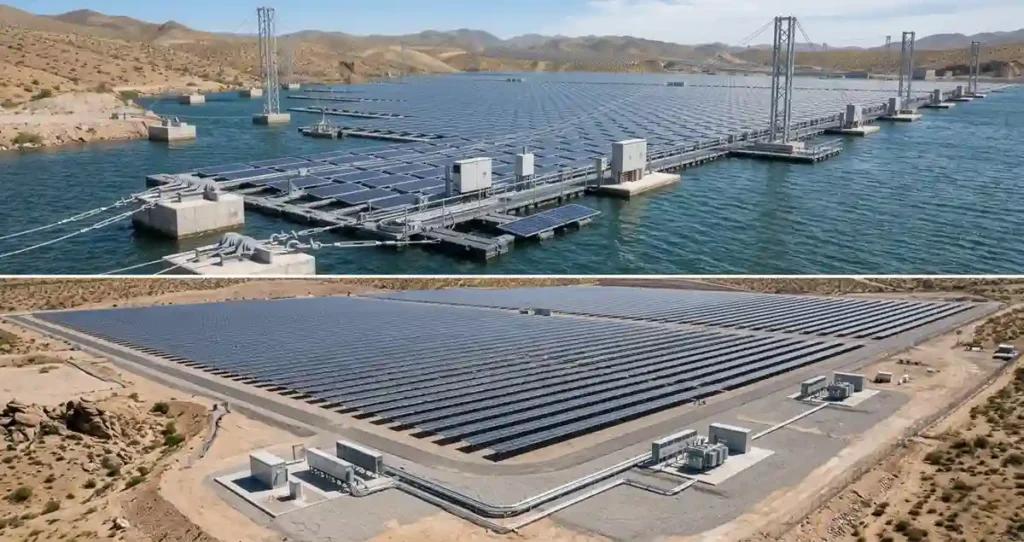
| Land use | Requires land — cost and competition with other uses | Uses water surface — no land cost | Eliminates land acquisition cost and land use conflict |
| Water evaporation | No effect | 50-70% evaporation reduction under array | Quantifiable secondary benefit in water-stressed regions |
| Shading on water body | N/A | Reduces algae growth in covered areas | Potential ecological benefit for some water body types |
6. Floating Solar Mounting System — US Permitting and Regulatory Framework
Floating solar installations on US water bodies require permits from multiple agencies — the specific combination depends on the water body type, ownership, and location. This is the most complex permitting environment of any solar mounting type, and it is the reason that floating solar projects in the US typically require 18 to 36 months of permitting before construction.
- US Army Corps of Engineers (USACE): Section 404 of the Clean Water Act permit required for any installation on navigable waters or waters of the United States. For enclosed private water bodies (farm ponds, private reservoirs) this may not apply — confirm with USACE district office for the specific site.
- State water quality agency: Section 401 Water Quality Certification from the state environmental agency is required in parallel with the USACE Section 404 permit. The state 401 certification confirms the installation meets state water quality standards.
- Bureau of Reclamation (for federal reservoirs): Any installation on a Bureau of Reclamation reservoir requires a land use authorization from the Bureau. Bureau of Reclamation has developed a floating solar policy framework and has authorized several installations on federal reservoir infrastructure.
- State utility commission: For grid-connected systems, the standard utility interconnection process applies — the water body location does not change the electrical interconnection requirements.
- Local building and zoning: Building permits are required for the shore connection infrastructure, inverter equipment, and any land-based components. Zoning review may be required for the overall installation depending on local regulations.
Engineer’s Note: The USACE Section 404 permitting process for floating solar is still evolving. The Corps has not issued nationwide guidance specifically for floating solar, which means individual district offices are making case-by-case determinations on whether floating solar installations qualify for Nationwide Permits (which have a faster 45-day review) or require Individual Permits (which can take 2 to 3 years). Engaging a permitting consultant with specific USACE floating solar experience is not optional on any US floating solar project above 100 kW — the permitting pathway selection alone can determine whether a project is financeable.
7. IRA Incentives Applicable to Floating Solar
Floating solar mounting systems qualify for the same IRA Section 48 Investment Tax Credit as land-based solar — the base 30% ITC applies to the full installed cost of the system including the floating platform, mooring system, and water-rated electrical infrastructure. Additional IRA adders that are particularly relevant to floating solar projects include:
- Energy Community Adder (10%): Many US floating solar sites — former mining areas, industrial water bodies, rural counties with fossil fuel employment history — qualify for the energy community bonus. This increases the total ITC to 40% for qualifying sites.
- Domestic Content Bonus (10%): Floating solar installations using domestically manufactured panels, racking, and structural components qualify for the domestic content adder. Several US HDPE pontoon manufacturers produce IRA-qualifying components.
- Low-Income Community Adder (up to 20%): For installations on or adjacent to low-income communities or Tribal lands, additional ITC adders apply. Some rural irrigation district floating solar projects in qualifying census tracts have accessed this adder.
The maximum combined ITC for a qualifying floating solar project — base 30% plus energy community, domestic content, and low-income adders — can reach 60% of installed cost. At this level, the economics of floating solar installations on qualifying sites are among the strongest of any solar project type in the US market.
8. Commissioning a Floating Solar Mounting System
- Platform integrity inspection: All pontoon modules inspected for damage, correct assembly, and absence of water ingress before the array is loaded. Any pontoon module showing water ingress is replaced before panel installation.
- Buoyancy verification: Array freeboard measured with full panel and equipment load. Freeboard must meet or exceed the design minimum at all measurement points across the array.
- Mooring tension verification: Mooring line tension measured using a dynamometer at each mooring point. Tension must be within the design range — under-tensioned moorings allow excessive drift; over-tensioned moorings overload anchors.
- Anchor proof load test: Minimum 5% of all anchors proof-loaded to 150% of design load before the mooring lines are connected to the platform. Any anchor that shows movement at proof load is rejected.
- Electrical insulation resistance test: Megohmmeter test on all DC circuits — string to string, string to ground — before energizing the system. Floating solar electrical systems are more vulnerable to insulation degradation from moisture than land-based systems; baseline IR values documented for comparison at future inspections.
- Shore cable dynamic test: Shore connection cable observed through a full water level variation cycle (if practical) or through simulated platform movement to verify no excessive strain at the shore termination point.
- Emergency retrieval test: Floating platform emergency retrieval procedure tested — verify that the platform can be moved to the shore access point and that the mooring system can be safely disconnected for maintenance access.
9. Floating Solar vs Other Non-Conventional Mounting Systems
| Comparison Factor | Floating Solar | Tensile Solar (Post 16) | Conventional Ground Mount (Post 6) |
| Site requirement | Water body — reservoir, pond, canal | Uneven terrain — slope, rocky, agricultural | Flat or gently sloping land |
| Foundation type | Mooring anchors in water bed | Rock or soil anchors at mast bases only | Driven piles or helical piers throughout array |
| Primary structural challenge | Buoyancy, wave loads, mooring design | Cable tension, anchor design, catenary geometry | Wind uplift, pile pull-out, rail span |
| Land use displaced | None — water surface | Minimal — anchor points only | Full array footprint |
| Secondary benefit | Water evaporation reduction; algae control | Agricultural use beneath; terrain access | None beyond energy generation |
| Engineering discipline required | Marine + solar engineering | Structural cable + solar engineering | Standard solar structural engineering |
| US permitting complexity | Highest — multiple agencies, water body permits | Moderate — building permit + environmental | Standard — building permit + solar permit |
| Relative capital cost/watt | 20-40% premium over standard ground mount | 10-30% premium on difficult terrain | Baseline |
| IRA bonus adder opportunity | High — energy community, low-income adders common | Moderate | Standard |
For tensile mounting on land-based challenging terrain — the closest alternative to floating solar for sites where land access is limited — see the Tensile Solar Mounting Systems guide. For the complete solar mounting system framework — including all conventional mounting types — see the Solar Mounting Systems hub. For ground mount foundation engineering that informs the shore-side infrastructure of floating solar installations, see the Solar Panel Ground Mounting Systems guide.
Frequently Asked Questions
What is a floating solar mounting system?
A floating solar mounting system is a specialized structure that supports photovoltaic panels on water surfaces using floating platforms, connectors, and anchoring systems.
Where are floating solar mounting systems used?
They are commonly installed on reservoirs, lakes, irrigation ponds, wastewater treatment ponds, and other large water bodies.
What are the advantages of floating solar systems?
Floating solar reduces land use, can improve panel efficiency through cooling effects, and helps reduce water evaporation from exposed surfaces.
How are floating solar panels anchored?
Floating solar systems use mooring lines, anchors, and water-level adjustment systems designed according to site conditions and wind/wave analysis.
Are floating solar mounting systems safe during storms?
Yes, when properly engineered. Designers consider wind loads, wave forces, water movement, and anchoring requirements to maintain system stability.
What materials are used in floating solar platforms?
Most systems use UV-resistant HDPE plastics, aluminum structures, stainless steel components, and corrosion-resistant materials suitable for long-term water exposure.
How long do floating solar mounting systems last?
Commercial floating solar systems are typically designed for 20 to 30 years depending on material quality, environmental conditions, and maintenance practices.
Is floating solar more expensive than ground-mounted solar?
Floating solar usually has higher installation complexity and costs due to platforms, anchoring, and water-based engineering requirements.
Related guides: Net Metering Complete Guide · AI Solar Optimization Guide · NEM 3.0 California Guide · BESS Battery Storage Guide