
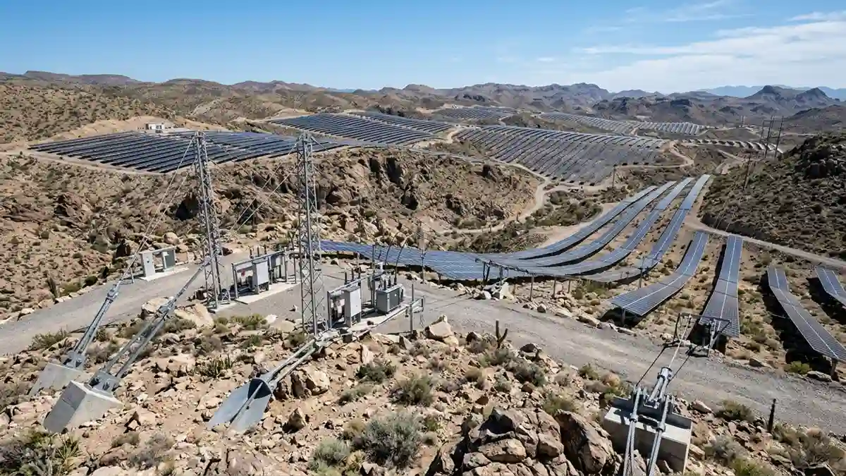
Tensile solar mounting systems — cable-suspended solar structures for uneven terrain, mountain slopes, river banks, and agrivoltaic sites where rigid racking cannot be used.
Every solar mounting system covered elsewhere on SolarVisionAI — rail systems, ground mounts, trackers — assumes one thing: that the terrain beneath the array is compatible with a rigid structural frame. Relatively flat ground where piles can be driven to uniform depth. A building roof with known structural capacity. A parking lot with a concrete foundation.
Tensile solar panels mounting systems exist for every site where that assumption breaks down. Mountain slopes where uniform pile depth is impossible. Rocky terrain where driven piles cannot achieve design embedment. River banks and canal margins where soil is too soft or saturated for conventional foundations. Agricultural land where the mounting structure must span large distances without intermediate columns to allow crop cultivation or vehicle access beneath.
These are not niche applications. As conventional flat ground sites become increasingly constrained in the US solar market — particularly in states where land cost and land use competition with agriculture are real project constraints — tensile mounting is transitioning from a specialty solution to a mainstream engineering tool for challenging sites.
This guide covers what tensile solar mounting systems are, how the structural engineering works, where they are the correct engineering choice, and what the design requirements look like for US commercial applications. For the broader solar mounting system context — including conventional ground mount, rooftop, and tracker systems — see the Solar Mounting Systems hub.
1. What a Tensile Solar Mounting System Is
A tensile solar mounting system supports solar panels by suspending them from a cable network under tension — rather than placing them on a rigid structural frame supported from below. The panels hang from or rest on tensioned steel wire ropes or structural cables that span between anchor points or support masts.
The fundamental structural principle is the catenary — the curve that a cable or chain naturally assumes when supported at two ends and loaded along its length. A tensioned cable between two anchor masts forms a catenary curve. Solar panels are attached to this cable network, either hung below the cables or supported on a series of transverse members that span between pairs of parallel cables.
The tension in the cables provides structural resistance to gravity loads and wind uplift — the cables pull toward their anchor points, and the anchor points transfer the cable tension to the ground or building structure. Unlike a rigid frame where loads are transferred through bending and compression of structural members, a tensile system transfers loads through pure tension — which is structurally efficient and uses significantly less material than equivalent rigid framing.
2. Types of Tensile Solar Mounting Systems

Catenary Cable Suspension System
The most widely used tensile configuration for solar applications. Two or more parallel steel wire ropes span between anchor masts or end posts, with solar panels attached along the length of the cables. The cable catenary curve provides clearance beneath the array — the height of the masts and the sag in the cable determine how much clearance is available under the panels.
This is the configuration used for agrivoltaic installations where crop cultivation or livestock grazing must continue beneath the solar array. By designing the mast height and cable tension to provide 3 to 5 meters of clearance beneath the panels, the array does not impede normal agricultural operations below.
Cable-Stayed Solar Structure
A cable-stayed tensile structure uses a central mast or pylon with stay cables radiating outward from the mast top to the panel frame perimeter. The stay cables hold the panel frame in position under gravity and wind loads. This configuration is most common for larger individual units — typically 50 kW to 500 kW per pylon — and is used over water bodies, rocky terrain, and other sites where intermediate ground support is not practical.
Tensioned Mesh System
A tensioned mesh system uses a grid of intersecting cables — both longitudinal and transverse — to create a two-dimensional cable network that supports the panel array. The mesh distributes load in two directions simultaneously, which allows longer spans and larger arrays than a single-direction catenary system. Tensioned mesh systems require more complex anchor design because cable tension acts in multiple directions at each anchor point.
Hybrid Tensile-Rigid System
A hybrid system uses conventional rigid ground mount structures at the perimeter — the masts or end frames — with tensile cables spanning between them to support the interior of the array without intermediate foundations. This is the most practical configuration for US commercial solar projects because it uses familiar conventional foundation engineering at the perimeter while eliminating the need for foundations across the full array footprint.
3. Where Tensile Solar Mounting Is the Correct Engineering Choice
| Site Condition | Conventional Rigid Mount | Tensile Mount | Why Tensile Wins |
| Mountain slope / steep terrain | Requires extensive grading or stepped foundation layout — expensive | Cable system follows the terrain profile — minimal grading | Terrain-adaptive; no cut-and-fill earthworks required |
| Rocky terrain / shallow bedrock | Driven piles cannot achieve design embedment — requires rock anchors or concrete piers | Rock anchors at mast bases only — rest of array spans on cables | Fewer foundation points in difficult substrate |
| Soft soil / high water table | Pile capacity limited — requires large diameter piles or deep embedment | Cable anchor design optimized for soil type — fewer but deeper anchors | Reduced number of foundation points reduces soil capacity demand |
| Agricultural land (agrivoltaic) | Low clearance systems restrict crop type and equipment access | High clearance cable system allows full agricultural use beneath | Best agrivoltaic clearance of any mounting system type |
| Canal / river margin | Erosion risk and fluctuating water table compromise conventional foundations | Cable-stayed system anchors on stable high ground away from erosion zone | Anchors away from problem soil |
| Large clear span required | Intermediate columns required — intrude on the cleared space | Cable system spans up to 50+ meters between supports | Eliminates intermediate columns entirely |
| Ecologically sensitive ground | Surface disturbance for every pile — minimized footprint is difficult | Only anchor points disturb the surface — minimal footprint | Lowest soil disturbance of any mounting system |
Engineer’s Note: The tensile mounting decision is not primarily about cost — it is about whether a rigid mounting system can physically be built on the site at all. On a 30-degree rocky hillside in West Virginia or a canal bank in California’s Central Valley, the question is not ‘is tensile cheaper than conventional?’ It is ‘tensile or no solar at all.’ That changes the financial conversation entirely.
4. Structural Engineering of Tensile Solar Mounting Systems
Cable Selection and Specification
The primary structural element in a tensile solar mounting system is the cable — typically a wire rope or structural strand. Wire rope consists of multiple wires twisted into helical strands, which are then twisted into the rope. Structural strand consists of wires wound helically around a central wire core with less twist than wire rope, giving higher stiffness for a given load.
For solar applications, structural strand is generally preferred because its higher stiffness reduces cable sag variation with temperature and load changes — which directly affects the panel tilt angle and clearance beneath the array. Cable specification requires: breaking strength (must exceed the design load times the required safety factor, typically 3.0 to 5.0 for primary structural cables), fatigue resistance (cables on outdoor structures experience cyclic loading from wind — fatigue rating must be verified for the site wind exposure), and corrosion protection (galvanized or stainless steel — stainless required within 1 mile of ocean exposure).
Anchor Design
The anchor — the point where the cable tension is transferred to the ground or building structure — is the most critical structural element in a tensile system. Every load in the cable network ultimately concentrates at the anchor points, which makes anchor design the controlling engineering calculation.
For ground anchors in soil, the anchor capacity is determined by the soil bearing resistance in tension (uplift) and shear. Ground anchors for tensile solar systems are typically one of three types:
- Driven steel anchor piles: H-piles or wide-flange sections driven to depth. Suitable for cohesive soils with adequate bearing capacity. Pull-out capacity determined by soil friction on the pile surface area.
- Helical anchors: Rotating screw anchors with helical bearing plates. Suitable for a wider range of soil types than driven piles. Both compression and tension capacity from helical bearing plates. Installation torque provides a direct indicator of anchor capacity — a significant quality control advantage.
- Rock anchors / soil nails: Grouted anchors drilled into rock or stiff soil. Used where driven or screwed anchors cannot achieve required capacity. Required in shallow bedrock conditions common on mountain and hillside sites.
Cable Tension Calculation
The design cable tension is determined by the load combination that produces the maximum tension in each cable segment. For a catenary suspension system, the critical load combinations are typically:
- Dead load (panel weight + cable weight) combined with maximum wind uplift — produces maximum tension in the upper anchor attachments
- Dead load combined with wind drag in the along-cable direction — produces maximum tension in the end anchor attachments
- Snow load (where applicable) combined with dead load — produces maximum sag and maximum tension in midspan cables
- Thermal contraction (cables shorten in cold weather) combined with dead load — produces maximum tension in all cables and maximum uplift on intermediate supports
Cable tension must be verified for all load combinations at the limit state (ultimate strength) and for serviceability (maximum sag and panel tilt variation under operating loads).
Mast and Support Structure Design
The mast or end frame that supports the cable system transfers cable tension to the foundation and provides the cable attachment elevation. Mast design must accommodate:
- Compression from the vertical component of cable tension — the mast is loaded in axial compression by the downward pull of the catenary cables
- Bending from the horizontal component of cable tension — the mast is pulled toward the array by the cable, creating bending about the base connection
- Torsion if cables attach at different heights or in multiple directions — common in cable-stayed and tensioned mesh configurations
- Wind load on the mast itself — at mast heights of 5 to 15 meters common in agrivoltaic applications, wind load on the mast can be significant
5. Tensile Solar Mounting — US Applications and Project Examples
Agrivoltaic — Dual Land Use
Agrivoltaic solar — combining solar power generation with active agriculture on the same land — is one of the fastest growing applications for tensile mounting systems in the United States. The US Department of Energy’s InSPIRE (Innovative Site Preparation and Impact Reductions on the Environment) project has documented multiple agrivoltaic installations demonstrating compatible land use, with tensile and elevated mounting systems enabling full agricultural equipment access beneath the array.
In states like Colorado, Oregon, Minnesota, and New York, agrivoltaic projects with elevated cable mounting are qualifying for agricultural land use designations while generating commercial solar revenue — a combination that significantly improves project economics in states where agricultural land is otherwise unavailable for solar development.
Mountain and Hillside Sites — Western US
In the mountainous terrain of Colorado, Idaho, Montana, New Mexico, and Arizona, large areas of solar resource coincide with terrain that makes conventional rigid mounting impractical. Tensile cable systems that span between rock-anchored masts can be installed on slopes up to 30 to 40 degrees without the grading and cut-and-fill earthworks that conventional ground mounts require on steep terrain.
The reduction in earthwork cost alone can justify tensile mounting on steep sites — cut-and-fill grading on a 20-degree slope for a 1 MW conventional ground mount can exceed $500,000. A tensile system on the same slope may require only rock anchor installation at the mast bases, at a fraction of that cost.
Canal-Top Solar — Water Conservation Application
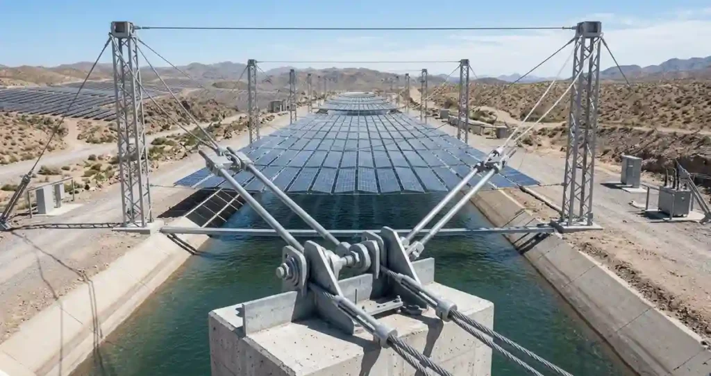
California’s Project Nexus — the first canal-top solar installation in the United States — demonstrated cable-supported solar panels mounted over the Turlock Irrigation District canal in Stanislaus County. The cable-suspended array reduces evaporation from the canal (reducing water loss by an estimated 63% per mile of covered canal), generates clean electricity, and uses land that has no competing agricultural or development use.
Canal-top solar using tensile mounting systems is now under active development in California, Arizona, Nevada, and Colorado — states where both water conservation and solar energy production are high-priority policy objectives. The IRA Section 48 Investment Tax Credit applies to these installations, and several states have added supplemental incentives for water-conservation-related solar applications.
Engineer’s Note: Canal-top solar is one of the most compelling dual-benefit applications I have reviewed in the US market. The structural challenge — spanning cables over an active irrigation canal at heights that allow maintenance boat access, while resisting the wind tunnel effect that canals create — is genuinely difficult engineering. The reward is a solar installation with essentially zero land use impact and a documented secondary benefit in water conservation that strengthens the project’s permitting position significantly.
Rocky and Challenging Terrain — Nationwide
Across the US, tensile mounting is seeing increasing use on sites that were previously considered unbuildable for solar — quarry reclamation sites, former mining areas with shallow rock, steep slopes in forested regions, and wetland-adjacent sites where conventional foundation equipment cannot operate. The common thread is that tensile systems need far fewer and more widely spaced foundation points than rigid racking, which reduces the area of disturbed ground and the total earthwork required.
6. Tensile Solar Mounting vs Conventional Systems — Engineering Comparison
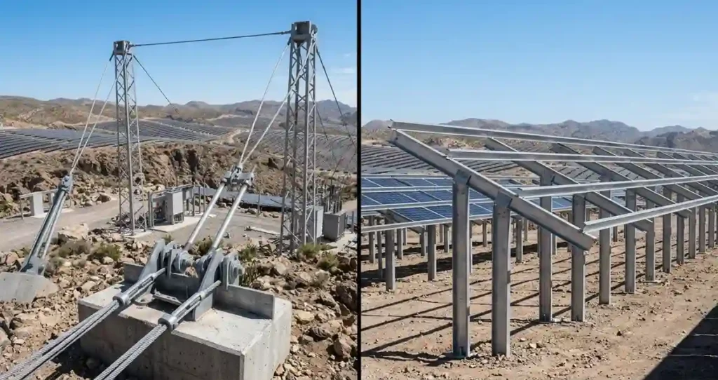
| Engineering Parameter | Conventional Rigid Ground Mount | Tensile Cable Mounting | Notes |
| Foundation points per MW | 150-300 pile locations | 8-40 anchor points | Tensile dramatically reduces foundation count |
| Terrain slope tolerance | 0-15° with standard racking; 15-25° with stepped layout | Up to 35-40° with cable system | Cable system is terrain-adaptive |
| Minimum soil depth required | 3-6 ft for driven piles | Varies — rock anchors work in shallow soil | Tensile can use rock anchors where soil is thin |
| Earthwork requirement | Moderate — grading for access and pile equipment | Minimal — only anchor locations disturbed | Major cost advantage on difficult terrain |
| Panel clearance height | 0.5-1.5m standard; up to 2.5m elevated | 2-6m achievable — agrivoltaic heights standard | Tensile provides full agricultural clearance |
| Wind load engineering | Standard ASCE 7-22 rigid panel method | Cable-specific dynamic analysis required | More complex wind engineering for tensile |
| Material quantity (steel) | Higher — full rigid frame required | Lower — cables are structurally efficient | Tensile uses tension, not bending — less material |
| Installation equipment | Pile driver + rail installation crew | Mast erection + cable tensioning crew | Different crew skills required for tensile |
| Maintenance access | Ground level throughout array | Cable and mast inspection required | Additional inspection points for tensile |
| Cost vs conventional (flat land) | Baseline | 20-40% premium on flat land | Tensile cost premium disappears on difficult terrain |
7. Design and Engineering Standards for Tensile Solar Mounting in the US
Tensile solar mounting systems in the United States are governed by the same primary structural standards as conventional mounting systems — ASCE 7-22 for wind and snow loads, the International Building Code (IBC), and relevant material standards (ASTM for steel, AWS for welds). However, tensile-specific design requirements add to these:
- ASCE 19-16: Structural Applications of Steel Cables for Buildings — the primary US standard for steel cable design in structural applications. Covers cable types, allowable stresses, connection design, and fatigue.
- Post-Installed Anchor Design: ACI 318-19 Chapter 17 for concrete anchors; IBC Chapter 18 for soil anchors. Rock anchor design typically follows FHWA ground anchor guidelines (FHWA-IF-99-015).
- IEC 62817: Solar tracker and mounting system standard — while written primarily for trackers, the structural and safety provisions apply to tensile mounting systems as novel mounting configurations.
- PE Stamp Requirement: Tensile solar mounting systems are structural systems that require a licensed Professional Engineer (PE) to stamp the structural drawings in every US jurisdiction. This is not negotiable — no AHJ will issue a building permit for a cable-supported solar structure without a PE-stamped structural drawing package.
Engineer’s Note: Tensile solar mounting is not a plug-and-play product you order from a catalog and install with a standard crew. Every installation is a custom engineering project. The cable sizing, anchor design, mast design, and connection details must be calculated for the specific site conditions — terrain, wind speed, snow load, soil type, panel layout. Any supplier or contractor who presents tensile mounting as a standard product installation without site-specific engineering should be disqualified immediately. The structural consequences of under-engineered cable anchor failure are catastrophic — a cable system that loses one anchor fails the entire array, not just a section.
8. Tensile Solar Mounting — Commissioning and Inspection Requirements
- Cable tension verification: Every primary cable tensioned to design specification using a calibrated tensionmeter. Tension recorded and compared to the engineering calculation. Under-tensioned cables increase sag and reduce panel clearance; over-tensioned cables increase anchor loads beyond design values.
- Anchor pull-out test: Minimum 5% of all anchors load-tested to 150% of design load. For rock anchors, 100% proof testing is standard practice. Any anchor that shows movement at proof load is rejected and redesigned.
- Mast vertical alignment: All masts plumbed to within 0.5% of vertical using a surveyor’s level. Out-of-plumb masts create eccentric loads at the base connection that were not in the design calculation.
- Panel tilt verification: Panel tilt angle measured at multiple locations across the array. Tilt variation greater than ±2 degrees from design indicates cable tension inconsistency or mast alignment error.
- Clearance verification: Minimum clearance beneath the array measured at midspan of the longest cable spans. Clearance must meet or exceed the design minimum (agrivoltaic installations: verify agricultural equipment clearance specifically).
- Cable end fitting inspection: All swaged or socketed cable end fittings inspected visually for correct assembly, full swage length, and absence of wire breakage at the fitting end. Cable end fittings are the most common failure point in tensile systems.
- Wind behavior observation: Array inspected under moderate wind conditions (15-25 mph) before final commissioning. Abnormal cable vibration (galloping or Aeolian vibration) indicates tuning is required — cable vibration dampers installed as needed.
9. The Future of Tensile Solar Mounting in the United States
Tensile solar mounting is at an inflection point in the US market. The technology is proven — cable-supported structures have been used in bridge engineering, stadium roofs, and transmission line construction for over a century. The solar-specific application is newer, but the engineering principles are well established.
Three factors are converging to accelerate adoption of tensile mounting in the US solar market:
- Land constraint: As the most accessible flat land in high-solar-resource regions is developed, project developers are increasingly evaluating sites that would have been bypassed five years ago. Tensile mounting opens these sites.
- Agrivoltaic policy support: The USDA and DOE have both published guidance supporting agrivoltaic development, and multiple states have enacted policies that facilitate agricultural land use permits for elevated solar installations. This policy environment directly benefits tensile mounting technology.
- IRA incentives: The Inflation Reduction Act’s energy community bonus credits, low-income community adder, and domestic content bonus all apply to tensile-mounted solar projects in eligible areas — which frequently include rural and mountainous regions where tensile mounting is most relevant.
For the complete foundation engineering context — including the pile types and anchor methodologies that ground tensile mast foundations — see the Solar Panel Ground Mounting Systems guide. For the broader solar mounting system taxonomy that tensile systems sit within, see the Solar Mounting Systems hub. For sites where conventional ground mounting is the right choice, see the Ground Mount vs Roof Mount Solar guide
Frequently Asked Questions
What is a tensile solar mounting system?
A tensile solar mounting system is a lightweight solar support structure that uses tensioned cables, anchors, and structural members to support photovoltaic panels while reducing the need for conventional heavy steel frameworks.
Where are tensile solar mounting systems used?
They are commonly used on difficult terrain including rocky land, uneven slopes, agricultural areas, flood-prone locations, and sites where traditional foundations are challenging.
Are tensile solar mounting systems cheaper than ground mount systems?
Not always. They may reduce material usage and foundation requirements, but they require specialized engineering, design, and installation expertise.
What are the advantages of tensile solar mounting systems?
Advantages include reduced structural weight, improved adaptability to difficult terrain, larger span capability, and potentially lower site disturbance.
What are the disadvantages of tensile solar mounting systems?
They require detailed structural engineering, accurate tension calculations, specialized installation methods, and careful maintenance of cables and connections.
Can tensile solar mounting systems handle high wind loads?
Yes, when properly engineered. Wind load analysis, cable tension design, anchoring, and structural calculations are critical for safe operation.
Are tensile solar structures suitable for utility-scale solar farms?
Yes. They can be suitable for utility-scale projects, especially where terrain conditions make conventional mounting systems difficult.
Related guides on SolarVisionAI.com
Solar Motion Sensor Flood Light: IP Ratings & Sizing Guide — solarvisionai.com/solar-flood-lights/
Commercial Solar Panel Installation — solarvisionai.com/commercial-solar-panel-installation/