Solar panel rail mounting kit — step-by-step installation sequence, kit verification checklist, bracket torque specs, slip-splice detail, and full commissioning verification.
A solar panel rail mounting kit is the physical instantiation of the mounting system design. Everything specified in the engineering drawings — the rail profile, the attachment hardware, the clamps, the fasteners — arrives on site as a kit that needs to be installed correctly for the engineering assumptions to hold.
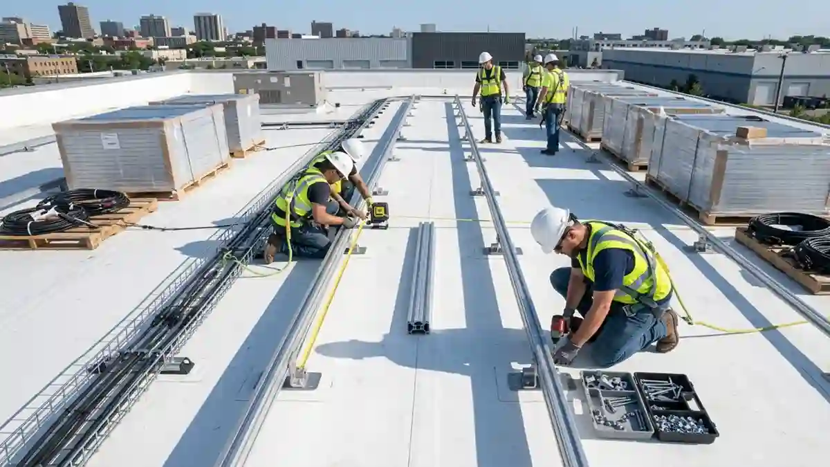
This guide covers the complete installation sequence for a commercial rail-mounted solar system, from kit verification through commissioning. It is the implementation companion to the Rail Mounted Solar Panels guide, which covers how the system works and what each component does. For the rail specification itself — alloy, profile, span tables — see the Solar Mounting Rails hub.
1. Kit Verification Before Installation Begins
The hardware submittal checklist that should precede this step is in the Solar Panel Mounting Brackets with Hardware guide. Once the submittal is approved, the following field verification applies:
- Verify rail alloy: Check the rail extrusion certificate for alloy designation. 6063-T5 or 6061-T6 as specified. Any discrepancy stops the installation until resolved — installing the wrong alloy means the structural calculation is invalid.
- Verify bracket type: Roof hook, L-foot, or seam clamp as specified for the roof type. Profile-specific components must match the specific roof profile on this project.
- Count fastener grades: Pull a sample of ten lag screws and check the head markings. 316 stainless should be marked ‘A4-70’ or ‘316’ on the head. If unmarked, verify with a magnet (stainless is non-magnetic).
- Verify clamp range: Measure the module frame height with a caliper. The clamping range specification is in the Solar Panel Mounting Brackets with Hardware guide.
- Check grounding hardware: Confirm WEEB clips or grounding lugs are in the kit and are the correct size for the rail T-slot and module frame geometry.
2. Roof Preparation
The roof-type-specific preparation requirements — rafter location methods, membrane inspection, and substrate assessment — are covered in the Roof Solar Panel Mounting Brackets guide. At minimum: locate all rafter positions and mark them on the roof surface before any bracket goes on the roof.
3. Bracket Installation
- Set bracket position: Mark the bracket centerline at the designed location per the structural layout drawing. Verify that the mark corresponds to a confirmed rafter location.
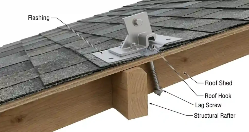
- Flashing installation (if applicable): On shingle roofs, lift the overlying shingle course and slide the flashing bracket under it. The flashing plate must overlap the shingle course below by a minimum of 2 inches. Apply butyl sealant to the underside of the flashing plate at the lag hole locations before setting.
- Lag screw installation: Pre-drill a pilot hole to the full required depth. Torque to specification with a calibrated torque wrench. Mark the fastener head after torquing. Do not use an impact driver for final torque.
- Sealant: Apply roofing sealant to the lag hole around the lag shank before installing the lag. Sealant on the underside of the flashing is the primary waterproof seal — not on the lag head.
Field Note: The most common installation error I find on rooftop solar inspections is under-torqued lag screws. The installer starts with a torque wrench and gradually switches to an impact driver ‘to go faster.’ By the end of the array, half the lags are at unknown torque. Torque to spec on every fastener, every one.
4. Rail Installation
- Set first rail: Lay the first rail section in the bracket saddles and align to the layout line. The rail should be level within ±3mm across the width of the array.
- Secure rail to brackets: Torque the rail-to-bracket connection hardware to specification. Verify the rail is captured in the bracket saddle and cannot rotate or lift out under upward force.
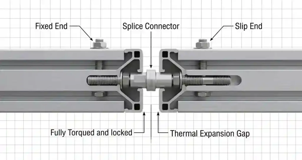
- Splice connection: At the fixed end, torque the clamping bolts to full specification. At the slip end, torque to 50% of the specified torque — allowing thermal expansion. This slip-joint detail is critical and is explained in the Solar Mounting Rails guide.
- Repeat for all rows: Verify alignment between rows — module clamp installation is significantly more difficult if rail rows are not parallel within ±5mm.
5. Module Installation
- Pre-stage modules: Lay modules on the rails in order, maintaining the string layout from the electrical design. Do not step on modules or use module frames as handholds during staging.
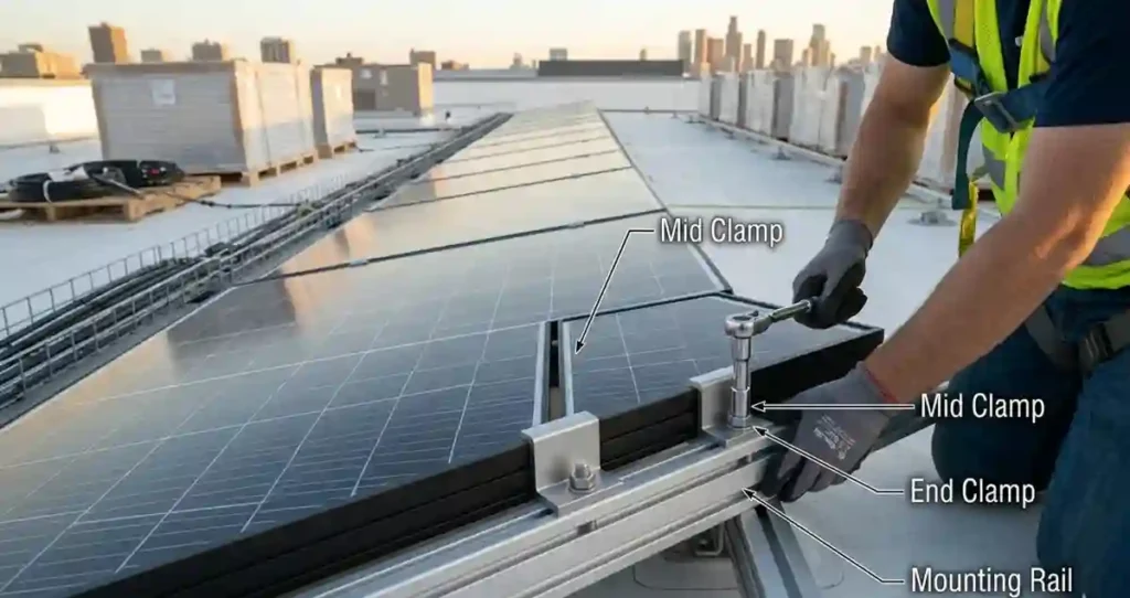
- Install end clamps at array start: End clamps are installed first at one end of each row before modules are moved into final position.
- Clamp each module: Slide the module into position against the installed end clamp or previously clamped module. Insert the mid clamp bolt into the T-slot between the two module frames. Position the mid clamp so it contacts both frames symmetrically. Torque to specification.
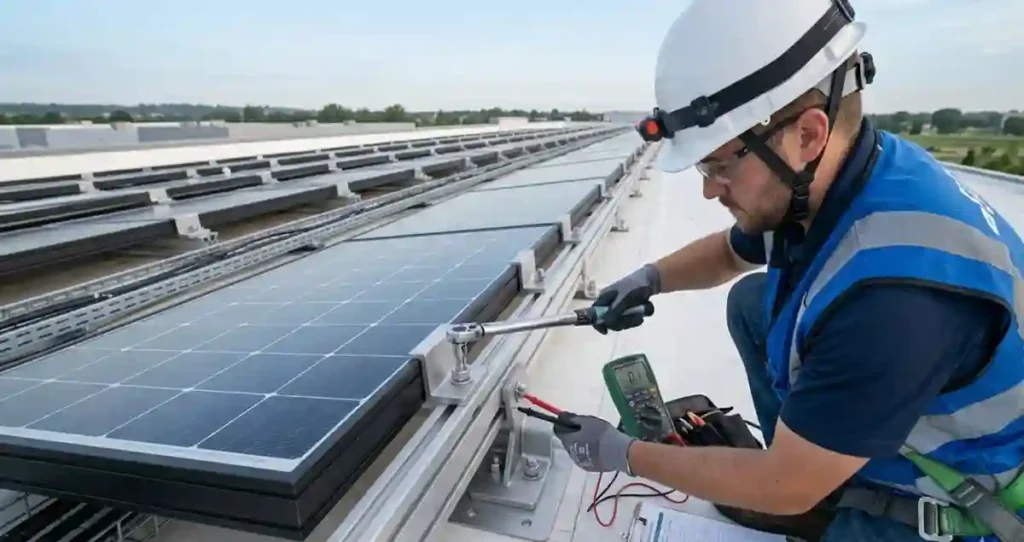
- Grounding: Install WEEB clips or grounding lugs at the frequency specified in the design. Verify continuity with a multimeter from module frame to grounding conductor before proceeding.
- End clamps at array end: Install end clamps at the last module in each row. Verify end cap is installed on all exposed rail ends.
6. Commissioning Verification — Mounting System
| Check Item | Method | Pass Criterion |
| Fastener torque | Calibrated torque wrench spot-check — 10% of all fasteners | All checked fasteners at design torque ±10% |
| Module clamp torque | Torque wrench on all accessible clamp bolts | All at design torque; no hand-tight fasteners remaining |
| Grounding continuity | Multimeter from module frame to ground bus | Resistance less than 1 ohm per NEC 690.47 intent |
| Rail level | Digital level across rail width and length | Level within ±5mm per 10 feet |
| Waterproofing | Visual inspection of all penetrations; wet test after installation | No sealant voids; no exposed lag shank |
| Splice thermal gap | Measure gap at slip splice after hot day | Gap present (not zero); within 0-6mm per temperature |
| Rail end caps | Visual inspection of all rail ends | End caps installed on 100% of exposed rail ends |
For the full structural engineering context, see the Solar Mounting Systems hub. For how the rail-mounted system works before you install it, see the Rail Mounted Solar Panels guide.
Frequently Asked Questions (FAQ)
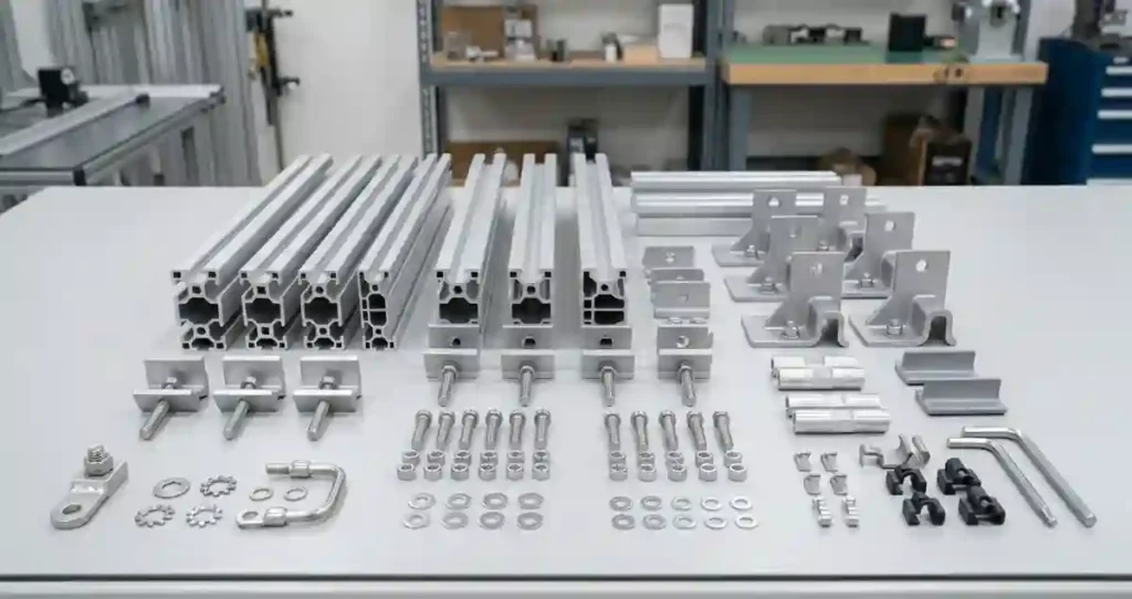
What is included in a solar panel rail mounting kit?
A solar panel rail mounting kit typically includes mounting rails, roof brackets or roof hooks, mid clamps, end clamps, splice connectors, grounding hardware, fasteners, and rail end caps required for installation.
How are solar mounting rails attached to a roof?
Solar mounting rails are attached through roof brackets or roof hooks that are fastened directly into structural members such as rafters or purlins. Flashing and sealants are used to maintain waterproofing.
Why is fastener torque important in solar installations?
Proper fastener torque ensures structural integrity and prevents loosening due to wind loads, thermal expansion, and long-term vibration. Under-torqued or over-torqued fasteners can compromise system safety.
What is a rail splice slip joint?
A rail splice slip joint allows aluminum mounting rails to expand and contract with temperature changes while maintaining structural continuity. This helps prevent rail buckling and bracket damage.
How is grounding verified during commissioning?
Grounding continuity is verified using a multimeter to confirm electrical continuity between module frames, mounting rails, and the equipment grounding conductor according to NEC requirements.
Related guides on SolarVisionAI.com
Solar Panel Installation: Complete Engineering Guide (2026)
Solar Panel Installation Cost: The Complete 2026 Breakdown
Commercial Solar Panel Installation: Engineering Guide 2026
When Is the Best Time to Install Solar Panels?
Solar Power System in 2026: Types, Cost, ROI & AI Optimization