
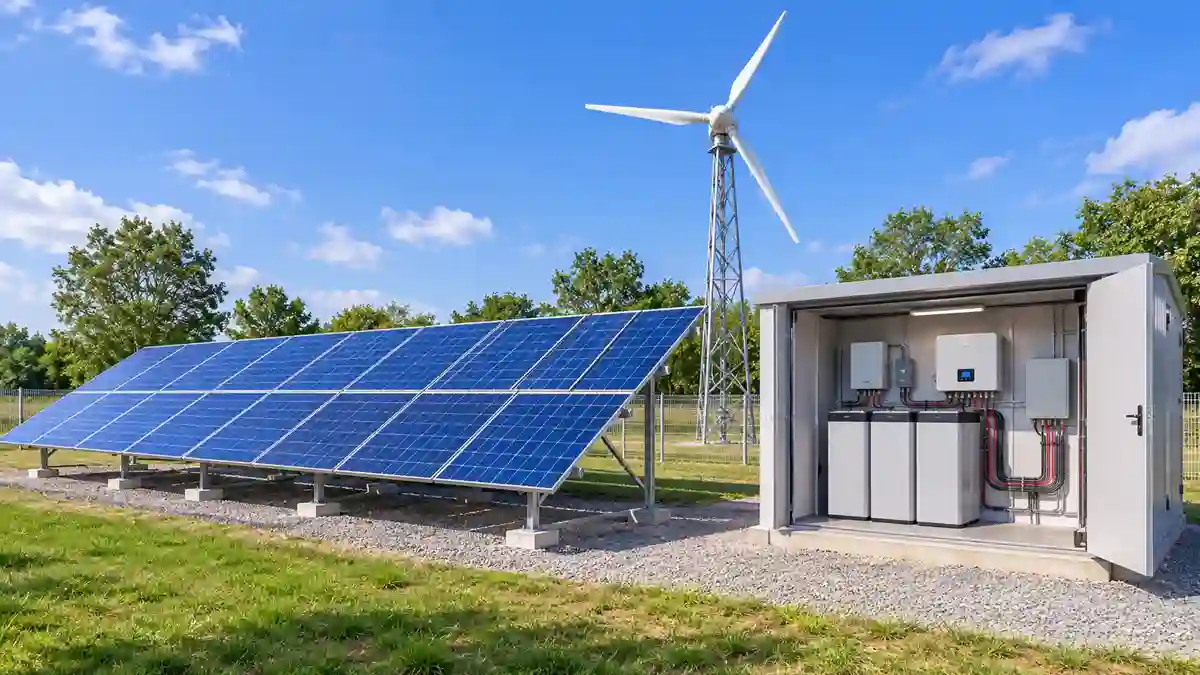
Learn how wind and solar hybrid controller work, how to connect their charging systems, and how to select inputs, battery controls, and protection.
When I evaluate a solar and wind hybrid installation, one of the first things I examine is how the two generation sources are controlled and connected to the battery and inverter system. Solar panels and wind turbines both generate electricity, but their electrical characteristics and operating requirements are different. Connecting them to a common energy-storage system therefore requires more than simply combining their output cables.
A wind and solar hybrid controller arrangement coordinates the charging paths from both renewable sources while maintaining the correct operating limits for the battery and associated equipment. In a typical off-grid design, the solar array uses an MPPT charge controller, while the wind turbine uses a dedicated wind controller designed for its generator and protection requirements.
The objective is to ensure that both sources can contribute energy safely without overcharging the battery, exceeding equipment limits, or creating unsafe turbine operating conditions.
This guide explains the controller architecture, input requirements, wiring principles, battery integration, protection equipment, and common design mistakes in solar and wind hybrid systems.
What Is a Wind and Solar Hybrid Controller?
A wind and solar hybrid controller arrangement manages electricity produced by solar panels and a wind turbine.
In many small off-grid installations, the arrangement uses two separate controllers:
- A solar MPPT charge controller for the photovoltaic array.
- A wind turbine controller for regulating wind-generated electricity.
Both charging systems may connect to a common battery bank if the controllers and battery are electrically compatible and their charging settings are correctly coordinated.
Some manufacturers also offer integrated hybrid controllers designed to accept both solar and wind inputs. These units must be checked carefully because their input ratings, control functions, and permitted turbine types vary.
Engineer’s Note: The term “hybrid controller” does not guarantee that a device can accept every type of solar panel and wind turbine. Always confirm the actual input specifications and supported electrical architecture in the manufacturer’s documentation.
How Solar and Wind Controllers Work Together
Solar and wind generation require different control methods.
Solar MPPT controller
Solar panels produce DC electricity. Their voltage and current vary with irradiance, temperature, shading, and operating conditions.
An MPPT controller adjusts the electrical operating point of the PV array to extract available power while regulating the battery charging process.
The PV array must remain within the controller’s maximum PV input voltage, current, and power specifications.
For more detail, see the MPPT solar charge controller guide.
Wind turbine controller
A small wind turbine may generate variable-voltage, variable-frequency AC, or DC, depending on its generator design.
A dedicated wind controller processes the turbine output and manages the charging and protection functions specified by the manufacturer.
Depending on the system, these functions may include:
- Rectification of variable AC output.
- Battery charging regulation.
- Diversion-load control.
- Electrical braking or shutdown functions.
- Overvoltage protection.
- Monitoring of turbine operating conditions.
The exact functions vary between turbine models.
Common battery connection
In a DC-coupled off-grid arrangement, the regulated outputs of the solar and wind charging systems may connect to a common battery bank.
The controllers must be compatible with the battery voltage and charging requirements. Their combined charging current must also remain within the battery manufacturer’s permitted limits.
A simplified arrangement is:
Solar PV array → Solar MPPT controller → Battery bank
Wind turbine → Wind controller → Battery bank
Battery bank → Inverter → AC loads
This is a conceptual architecture, not a universal wiring diagram. The manufacturer’s connection arrangement takes priority.
For a broader overview of the complete installation, see the solar and wind hybrid system guide.
Wind and Solar Hybrid Controller Wiring
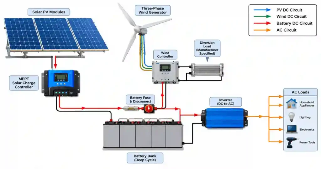
Correct wiring is essential because the solar and wind sources do not behave identically.
1. Solar PV input wiring
The solar panels connect to the PV input of the solar MPPT controller.
Before connecting the PV array, verify:
- Maximum PV open-circuit voltage (Voc).
- Maximum PV short-circuit current (Isc).
- Permitted operating voltage range.
- Maximum PV power.
- Series string configuration.
- Cable current rating.
- DC isolation and overcurrent protection requirements.
PV string voltage must be calculated at the lowest expected module temperature, because open-circuit voltage increases as module temperature falls.
The array must remain within the controller’s absolute maximum voltage under all expected conditions.
2. Wind turbine input wiring
The wind turbine connects to the dedicated input specified by its controller manufacturer.
For a three-phase permanent-magnet generator, the controller may accept three-phase variable AC and rectify it internally. Other turbines may have a different output arrangement.
Before connecting the turbine, confirm:
- Generator phase configuration.
- Rated and maximum operating voltage.
- Maximum current or power.
- Controller input compatibility.
- Required cable size.
- Required turbine isolation arrangement.
- Diversion-load or braking requirements.
Never connect a wind turbine to a PV input simply because the voltage appears similar. The electrical behaviour and control requirements may be different.
3. Battery connection
The solar and wind controllers may share a battery bank if the manufacturers permit this arrangement.
The battery connection should include correctly rated conductors and the specified overcurrent protection. Cable length, current, voltage drop, installation method, and ambient temperature all influence conductor selection.
Check the following before commissioning:
- Battery nominal voltage.
- Battery charging voltage settings.
- Maximum combined charging current.
- Maximum battery charge current.
- Controller charging profiles.
- Battery BMS limits.
- Battery temperature operating range.
For battery selection and installation considerations, see the solar battery installation guide.
4. Inverter connection
The inverter connects to the battery or approved DC bus according to its manufacturer’s instructions.
Its continuous power rating, surge capacity, DC input range, and protection requirements must match the system design.
Do not connect the wind turbine output directly to a conventional solar hybrid inverter unless the inverter manufacturer specifically supports that connection.
The hybrid inverter guide explains the main inverter configurations and selection considerations.
What Inputs Should a Hybrid Controller Support?
The required inputs depend on whether the system uses separate controllers or an integrated hybrid unit.
| Input or connection | Purpose | Design check |
|---|---|---|
| PV input | Receives solar array electricity | Maximum Voc, Isc, power and MPPT range |
| Wind generator input | Receives turbine output | Generator type, voltage, current and power |
| Battery terminals | Connects to energy storage | Battery voltage, polarity and current limits |
| Diversion-load output | Routes excess wind energy to a suitable load | Load rating and controller compatibility |
| Temperature sensor | Monitors battery or equipment temperature | Sensor type and permitted operating range |
| Communication port | Allows monitoring or configuration | Supported protocol and device compatibility |
| Remote shutdown or brake connection | Provides a specified turbine control function | Manufacturer-approved wiring and operating logic |
Not every controller includes every connection. Some functions may be handled by separate equipment.
Engineer’s Note: Do not select a controller based only on its advertised wattage. Check its complete electrical specification, including maximum input voltage, continuous current, short-circuit conditions, battery voltage, thermal limits, and supported protection functions.
What Is a Wind Turbine Diversion Load?
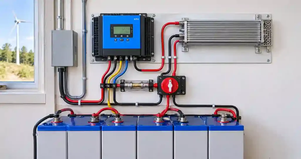
A diversion load is an electrical load used in certain small wind battery-charging systems to absorb excess turbine energy when the battery reaches its charging regulation limit.
For example, when the battery is sufficiently charged, the wind controller may direct some or all of the turbine’s available electrical power to a compatible resistive load rather than allowing the battery voltage to rise beyond its permitted limit.
A diversion load may be designed as a resistive heating element, but its rating and control method must match the turbine and controller.
A diversion load is not simply an optional accessory that can be added to any wind turbine. It is part of a specified control and protection arrangement where the manufacturer requires it.
Why is a diversion load important?
Depending on turbine design, removing the electrical load or allowing the battery to reach its upper voltage limit can create an unsafe or damaging operating condition.
The turbine may need an alternative electrical load, braking function, or other approved method of controlling its operation.
The correct solution depends on the turbine’s design.
Field Note: Never assume that opening the turbine’s electrical circuit is a safe way to stop it. Some wind turbines require a specific sequence involving a controller, diversion load, shorting or braking arrangement. Follow the manufacturer’s shutdown procedure.
Battery Charging Coordination
When two charging controllers operate on the same battery bank, their charging behaviour must be considered together.
For example, the solar controller may enter its absorption or float stage while the wind controller continues receiving power from the turbine.
The battery must remain within its permitted charging voltage and current limits even when both sources are producing power.
Important checks include:
- Both controllers must support the battery’s nominal voltage.
- Charging voltage settings must follow the battery manufacturer’s specifications.
- Combined charging current must not exceed the battery’s permitted limit.
- The battery BMS must support the expected charging conditions.
- Temperature limits and sensor arrangements must be considered.
- The wind controller’s excess-energy management must remain operational.
Example: Combined charging current
Assume an illustrative 48 V battery system has:
- Solar controller charging current: 40 A
- Wind controller charging current: 25 A
The theoretical combined charging current is:
40 A + 25 A = 65 A
If the battery manufacturer’s maximum permitted charging current is 80 A, the calculated combined current is below that limit.
However, this simple comparison does not complete the design. The battery BMS, cable ratings, protection devices, controller behaviour, temperature limits, and charging settings must also be checked.
If the battery’s permitted charging current were only 50 A, the controllers would need a suitable current-limiting or coordinated charging arrangement.
Engineer’s Note: Do not size the battery charging system by checking each controller separately. The combined charging current from all active sources must be evaluated against the battery and BMS specifications.
For additional battery capacity guidance, use the solar battery size calculator.
Electrical Protection for Solar and Wind Hybrid Controllers
Protection must be designed around the characteristics of each energy source.
Solar PV protection
Depending on array configuration and applicable electrical requirements, PV protection may include:
- DC isolators.
- String fuses where required.
- DC-rated circuit breakers.
- Surge protection devices.
- Correctly rated PV cables and connectors.
- Earthing and bonding.
PV protection must be selected for the maximum possible string voltage and current, including the relevant design conditions.
Wind turbine protection
Wind turbine protection is more equipment-specific.
It may include:
- Turbine disconnect or isolation equipment.
- Controller overvoltage protection.
- Diversion-load protection.
- Manufacturer-specified braking or shutdown arrangement.
- Surge protection where required.
- Suitable generator and battery cable protection.
- Tower and equipment earthing.
A wind turbine can continue rotating when the battery is full, or the electrical load is disconnected. The turbine’s specified control and shutdown arrangement must therefore remain effective.
Battery and inverter protection
Battery and inverter protection may include:
- Battery fuse or DC circuit breaker.
- Battery disconnect.
- Correctly rated DC cables.
- BMS protection.
- Inverter AC output protection.
- AC and DC surge protection where required.
- Appropriate earthing and bonding.
The power inverter technical guide provides additional information about inverter selection and electrical considerations.
Common Wiring and Controller Selection Mistakes
Using a solar MPPT controller for a wind turbine
A conventional solar MPPT controller is not automatically suitable for a wind turbine. Wind generation requires compatible regulation and, where specified, turbine-specific excess-energy and braking functions.
Ignoring the maximum PV input voltage
PV open-circuit voltage can increase at low temperatures. A string that appears acceptable under warm conditions may exceed the controller’s maximum voltage during colder conditions.
Undersizing the diversion load
A diversion load must be capable of handling the power and operating conditions specified by the turbine controller manufacturer.
Ignoring combined battery charging current
Two controllers may each be within their individual ratings while their combined output exceeds the battery’s permitted charging current.
Using incorrect cable protection
A breaker or fuse must be rated for the relevant DC or AC circuit, voltage, current, and fault conditions. An AC-rated device should not be assumed suitable for a DC circuit.
Disconnecting a wind turbine incorrectly
A wind turbine may require a specific shutdown and braking sequence. Disconnecting its output without following the manufacturer’s procedure can create an unsafe condition.
How AI Can Help Monitor Solar and Wind Hybrid Controllers
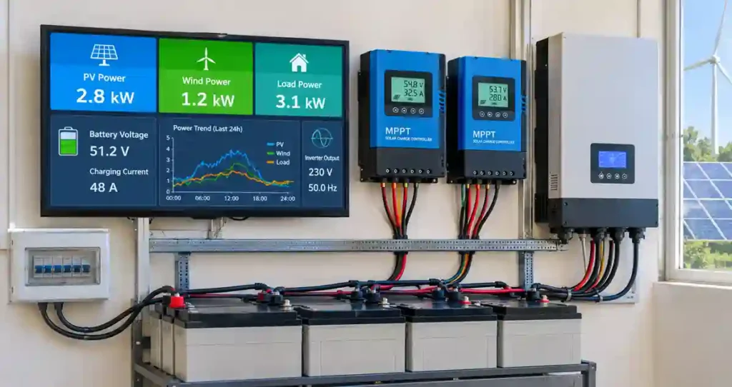
AI-based monitoring can analyze PV output, wind generation, battery state of charge, charging current, and controller alarms to identify unusual operating patterns.
It may help predict energy availability, identify charging inconsistencies, and support maintenance planning.
For example, if wind generation repeatedly drops while the measured wind conditions remain favourable, monitoring data may help engineers investigate a possible turbine, controller, wiring, or sensor problem.
Field Note: AI monitoring is useful only when the underlying measurements are reliable. It does not replace the wind controller, MPPT regulation, battery BMS, diversion-load protection, or manufacturer-approved braking system.
Commissioning Checklist
Before placing a solar and wind hybrid charging system into operation, verify the following:
- Confirm the controller model and manufacturer documentation.
- Check PV string voltage and current calculations.
- Verify wind generator type and controller compatibility.
- Confirm battery nominal voltage and charging settings.
- Check combined charging current against battery and BMS limits.
- Verify diversion-load rating and connection, where required.
- Check DC cable sizes and voltage drop.
- Confirm fuse and breaker ratings.
- Verify polarity and terminal tightness.
- Confirm earthing and surge protection arrangements.
- Test controller alarms and monitoring functions.
- Follow the manufacturer’s turbine startup and shutdown procedure.
- Record the final configuration and commissioning measurements.
Field Note: Commissioning should be documented, not just completed. Record the PV string configuration, wind controller settings, battery voltage, charging current, protection ratings, and inverter settings. This information is valuable for future troubleshooting and maintenance.
Applicable Electrical Codes and Engineering Standards
The design and installation of a solar and wind hybrid controller system should follow recognized electrical safety standards and the requirements adopted by the local authority having jurisdiction.
The following standards are particularly relevant:
- NFPA 70 – National Electrical Code (NEC): Provides requirements for safe electrical installations. Relevant provisions cover photovoltaic systems, small wind electric systems, energy storage and interconnected power sources. Commonly referenced articles include Articles 690, 694, 705 and 706; confirm the numbering and requirements in the edition adopted by the project jurisdiction.
- IEC 61400-2: Covers the safety, design, installation, maintenance and operation of small wind turbines, including their electrical and mechanical protection.
- UL 1741: Covers inverters, converters, charge controllers and interconnection equipment used with distributed energy resources.
- IEEE 1547-2018: Establishes technical requirements for interconnecting distributed energy resources with electric power systems.
- IEEE 1547.1-2020: Defines testing procedures for verifying equipment compliance with applicable interconnection requirements.
Engineer’s Note: These standards do not replace equipment manufacturers’ installation instructions. Controller ratings, conductor sizing, overcurrent protection, earthing, battery charging limits and wind turbine shutdown arrangements must be verified against the actual equipment documentation and applicable local regulations.
Frequently Asked Questions
Can solar and wind use the same charge controller?
They can use a shared controller only if it is specifically designed and approved for both sources. Otherwise, separate solar and wind controllers are generally used.
Can a solar MPPT controller control a wind turbine?
Not automatically. A standard PV MPPT controller is designed for solar modules and may not provide the turbine regulation, diversion-load control, or braking functions required by a wind turbine.
Can two charge controllers charge one battery bank?
Yes, if both controllers support the same battery system and their combined charging behaviour remains within the battery manufacturer’s permitted limits.
What is a wind turbine diversion load?
It is a compatible electrical load used by certain wind charging systems to absorb excess turbine energy when the battery reaches its charging regulation limit.
Does every wind turbine need a diversion load?
No. The requirement depends on the turbine’s design and the manufacturer’s specified control and protection arrangement.
Can I connect a wind turbine directly to a hybrid inverter?
Only when the inverter manufacturer specifically supports the turbine and the proposed connection method. A conventional PV input should not be assumed compatible with wind turbine output.
How do I choose a wind turbine charge controller?
Check generator compatibility, maximum voltage, current and power ratings, battery voltage, charging profile, diversion-load requirements, braking functions, environmental ratings, and manufacturer support.
Final Thoughts
A reliable solar and wind hybrid system depends on correctly coordinating two different generation sources. The solar MPPT controller regulates PV charging, while the wind turbine controller manages the turbine’s electrical output and its specified protection functions.
Both charging systems can contribute to a common battery bank when their electrical characteristics, charging settings, and protection arrangements are compatible.
My recommendation is to select the controllers only after confirming the PV array specifications, turbine generator characteristics, battery charging limits, inverter architecture, and protection requirements. Correct wiring and commissioning are just as important as selecting the right equipment.
Related guides
- Solar and Wind Hybrid System: Design, Sizing, Cost, and Working
- Home Wind Turbine: Cost, Output, Sizing and Is It Worth It?
- Home Wind Turbine: Cost, Output, Sizing and Is It Worth It?
Related guides on SolarVisionAI.com
- Monocrystalline Solar Panels 2026: Still Worth It or Hype
- Polycrystalline Solar Panels: Worth Buying in 2026?
- Thin-film Solar Panels: When They Beat Silicon (2026)
- BIPV Solar Panels: Building-Integrated PV Complete Guide
- Portable Solar Panels: Engineer’s Buyer’s Guide 2026
- CPV Solar Panels: Concentrated Photovoltaic Explained
- Skin Solar Panel: What “Solar Skin” Actually Means
- Solar Fence Post Lights: Cap Sizes, Types & Install Guide
- Bifacial Solar Panels in 2026: How to Boost Energy Output
- Solar Charge Controller: The Complete Guide
- MC4 Connectors: Solar Safety & Installation Guide
- Solar Panel Types, Efficiency & Benefits
- Solar Water Pump Guide
- Commercial Solar Panel Installation: Engineering Guide
- Solar Fence Post Lights: Cap Sizes, Types & Install Guide
- BESS — Battery Energy Storage System Guide
- Commercial Solar Panel Installation
- Solar Refrigerator & DC Fridge — Complete 2026 Guide
- Bifacial Solar Panel Albedo Effect Guide
- TOPCon: Why TOPCon Solar Panel is a Proven Smart Investment in 2026
- HJT: Why TOPCon Solar Panel is a Proven Smart Investment in 2026
- PERC: PERC Solar Panel: Still Relevant or Already Outdated?
- Perovskite: Perovskite Solar Panels: The 2026 Reality Check
- N-Type vs P-Type: N-Type vs P-Type Solar Panels: Honest Comparison
- ABC: ABC (all back contact) Solar Panel: Back Contact Technology Explained
- IBC: IBC Solar Panels: Interdigitated Back Contact Guide
- Tandem: Tandem Solar Panels: Are Stacked Cells Ready for Rooftops?